Building a D Latch with NAND gates (74LS00).
Here's a quick demo of it in action..

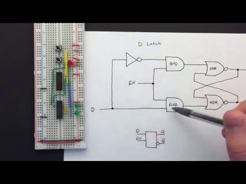
The Gated D latch:
- sets the complementary outputs (Q & ~Q) based on a single input bit ("D" i.e. data)
- out changes are synchronous i.e. no clocking required - they change immediately
- new data is only latched when the enable input is set
- if enable input is not set, the outputs (Q & ~Q) remain latched at their last value
The gated D latch is a fundamental 1-bit memory unit, and is at the core of much digital logic design.

| E | D | Q(t+1) | ~Q(t+1) |
|---|---|---|---|
| 0 | 0 | Q(t) | ~Q(t) |
| 0 | 1 | Q(t) | ~Q(t) |
| 1 | 0 | 0 | 1 |
| 1 | 1 | 1 | 0 |
There are various combinations of gates that can be used to construct a D latch.
I'm going to test a design based on an SR NAND latch, which means a single 74LS00 (quad two-input NAND):

Alternatively this can be built based on an SR NOR latch:
.svg)
Great explanations of the D latch and D Flip-Flop..
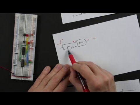
I'm building this first on a breadboard using a single 74LS00 (quad two-input NAND), LED indicators and manual inputs.
- the enabled input uses one pole of a DPDT switch
- the data input uses a push-button with the default position low with a 1kΩ pull-down resistor
NB: the pull-down resistor can't be too stiff with the 74LS00. For example, a 10kΩ pull-down resistor allows the input to float a little too high and corrupt the input.


- 74LS00 datasheet
- The D Latch - allaboutcircuits
- Gated D latch - wikipedia
- The D Flip-Flop
- D latch - Ben Eater
- D flip-flop - Ben Eater
- 7400 Series datasheets
- ..as mentioend on my blog