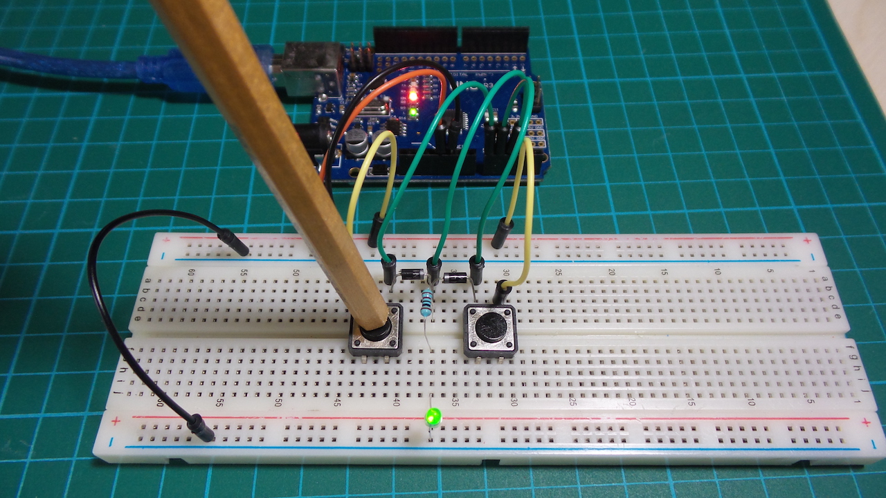
Test the basic diode-logic OR gate
Diode logic was used extensively in early computers but is largely obsolete now, since it cannot isolate inputs or outputs without additional circuitry, and there will be at least a 1-diode voltage drop to deal with across the gate.
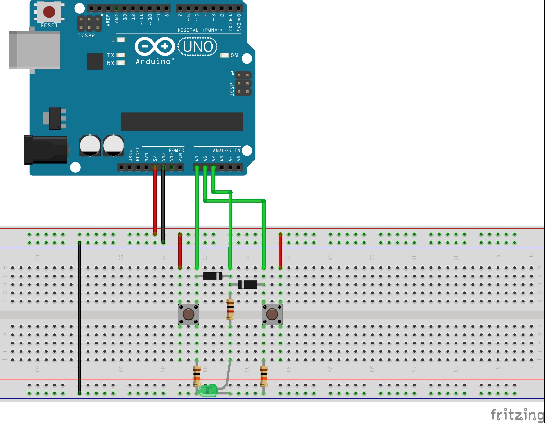
It is interesting to see how various logic gate may be realised with diodes (and resistors) alone. Here is the basic OR gate.
Output is high given any of the inputs are high:
| A | B | OUT |
|---|---|---|
| 0 | 0 | 0 |
| 0 | 1 | 1 |
| 1 | 0 | 1 |
| 1 | 1 | 1 |
In this circuit with VCC of 5V and where Vf is the diode forward voltage of approx. 0.7V:
- Out logical "0" == 0V
- Out logical "1" == VCC - 1 x Vf ~> 4.3V
Pull-down resistors R2,R3 are used to prevent floating inputs.
The Arduino is not a core part of the circuit. It only does the following:
- provides +5V power supply (for convenience)
- measures the input and output voltages for plotting. It uses the PlotNValues sketch for this purpose.
Here's a sample trace. The upper trace is the output, the lower traces the inputs.


- Diode Logic - wikipedia
- 1N4001-1N4007 datasheet
- Engineer's Mini-Notebook - Basic Semiconductor Circuits; Forrest M. Mims III