Test a low-speed square wave oscillator using NOR gates.
Here's a quick video of the circuit in action:

This circuit demonstrates a free-running oscillator based on two NOR gates - using 2/4 of a 74LS02. I got the idea from Beginning Digital Electronics Through Projects which features a NOR gate metronome. The circuit needed a few tweaks to get running with a different NOR IC and supply voltage.
It's quite an interesting circuit, as you wouldn't necessarily think that two NOR gates could form a reliable oscillator.
The basic operating principle (as far as I understand it so far):
- when NOR(1) output is high, NOR(2) input is high and output low, and vice versa
- the switching of the NOR(1) gate input is delayed by the RC network:
- when NOR(2) output is low, C1 charges through the R4/R5 series from the NOR(1) high output
- this raises the voltage on NOR(1) input to such point that the NOR(1) output switches low
- then with NOR(2) output high, C1 discharges through R3 to the NOR(1) input to such point that the NOR(1) output switches high
- rinse and repeat
The Arduino is not really a core part of the circuit. It only does the following:
- provides +5V power supply (for convenience)
- measures the input and output voltages for plotting
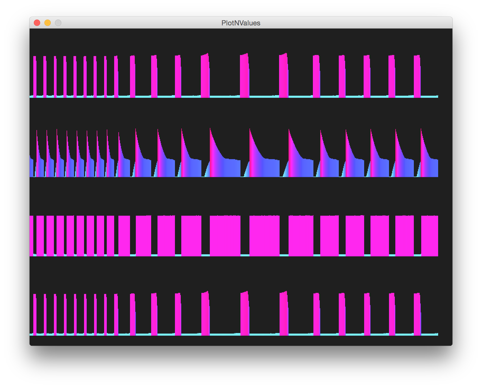
Here's a sample trace recorded using the PlotNValues sketch. It has four traces, from top to bottom:
- output of the first OR gate (which I belatedly realised was exactly the same node as the first trace, hence excluded from the schematics)
- inputs to the first OR gate
- output of the second OR gate (tapped as the main output)
- inputs to the second OR gate


- 74LS02 datasheet
- A similar circuit may be found in "Project 17 - NOR Gate Metronome" from Beginning Digital Electronics Through Projects