Demonstrate how analog pins can also be used as a digital GPIO
This is a simple demonstration of a tip shared by [email protected] in the Arduino Tips and Tricks email newsletter
On the Arduino Uno, there are 6 analog pins. While we'd normally use AnalogRead to read A/D values and AnalogWrite to write PWM, they can also be used as GPIO digital pins.
The conventional analog pin mnemonics can be used:
pinmode(A0, INPUT);
int in = digitalRead(A0);
If desired it's also possible to use the raw pin number (if driving pins algorithmically for example).
Pin definitions are found in the pins_arduino.h. For the Uno, the
To use them as digital inputs, just use this reference table:
| Analog Pin | Pin | pins_arduino.h definition |
|---|---|---|
| 0 | 14 | static const uint8_t A0 = 14; |
| 1 | 15 | static const uint8_t A1 = 15; |
| 2 | 16 | static const uint8_t A2 = 16; |
| 3 | 17 | static const uint8_t A3 = 17; |
| 4 | 18 | static const uint8_t A4 = 18; |
| 5 | 19 | static const uint8_t A5 = 19; |
Using the pin number explicitly:
pinmode(14, INPUT);
int in = digitalRead(14);
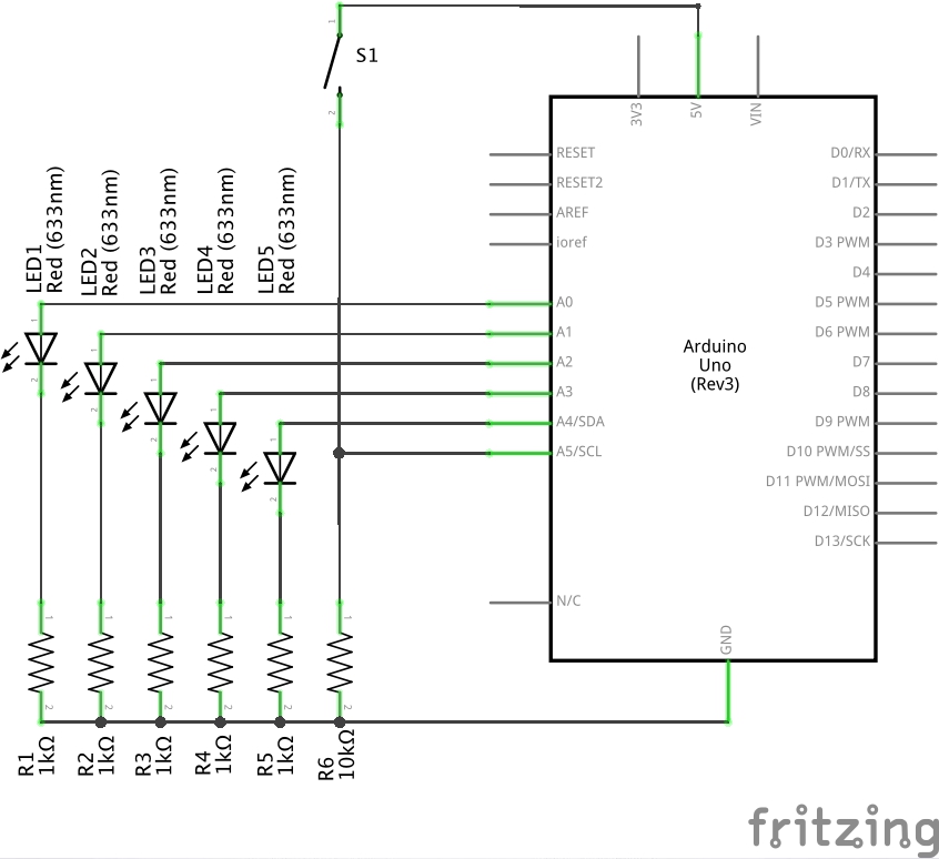
The DigitalInputWithAnalogPins.ino sketch is a simple exercise of analog pins A0..A5 using both digital input and output.
Five pins A0..A4 are set to sequentially drive corresponding LEDs at about 5mA.
A pushbutton is read on A5. Pressing the button reverse the LED sequence.


- Arduino Tips and Tricks email newsletter
- AnalogInputPins - arduino.cc tutorial
- DigitalRead - arduino.cc reference
- ..as mentioned on my blog