-
Notifications
You must be signed in to change notification settings - Fork 0
Breakdown
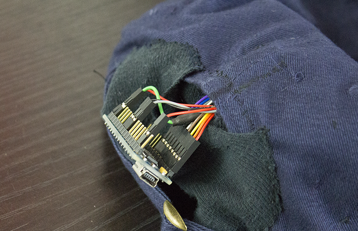
The hat I built uses 8 vibrator motors to indicate direction, and a Honeywell HMC5883L 3-axis digital magnetometer (using the GY-273 breakout board) to determine the compass heading, both of which are controlled by an Arduino nano; power is supplied by battries from an old smartphone2, along with a step up transformer. The hat I got for free at a conference, courtesy of Triangle Analytical, Inc.
The magnetometer is mounted on the underside of the visor/brim of the hat, and the motors are inserted into small pockets sewn into the band. The battery, step up transformer and most of the connections are sewn into the underside of the crown. The most obtrusive part of my prototype is the Arduino itself, mainly because the one I bought already had DIP headers soldered into it; ideally, I would just use wire-to-wire connections for everything to lower the profile of the component, but because I don't want to desolder the long DIP headers, so I simply added a small pocket to the back into which I've slipped the breakout board.
One significant caveat of this design is that, from what I understand, some step-up transformers have capacitors that are not necessarily rated to the maximum voltage of voltage regulator, so if you accidentally turn the potentiometer too high, the capacitors can explode. This is not something I would enjoy happening to a component pointed directly at my skull, so rather while the intuitive way to mount the step-up transformer is facing in, I suggest mounting it facing out; I've found that it helps to use styrofoam standoffs to prevent the thread from fraying and loosening in this configuration. This simultaneously minimizes the chance that I'll accidentally turn the screw on the potentiometer and, if the capacitors do explode, they'll hopefully explode away from my head, not towards it.
For simplicity's sake, in the prototype the vibrator motors are actuated directly using the digital outputs of the Arduino, but these are primarily logic outputs and were not designed to drive circuits, so it may be better to use something like a CD74HC4067 16-channel digital multiplexer hooked up to the output of the step-up transformer. You can also try using 1 kΩ AD5254 digital potentiometers, which make it easier to control the vibration intensity, but requires 1 IC for every 4 channels. In my experience, both seem to have an "on" voltage of approximately 50 Ω.
Text, images and source code released under a Creative Commons Attribution 4.0 International License (CC-BY 4.0). If you'd like to use anything under other terms, please contact me to work something out.
