###Overview
The Raspberry Pi has 40 GPIO pins that provide numerous capabilities, including I2C, SPI, and general digital I/O. Information about the pins can be found here.
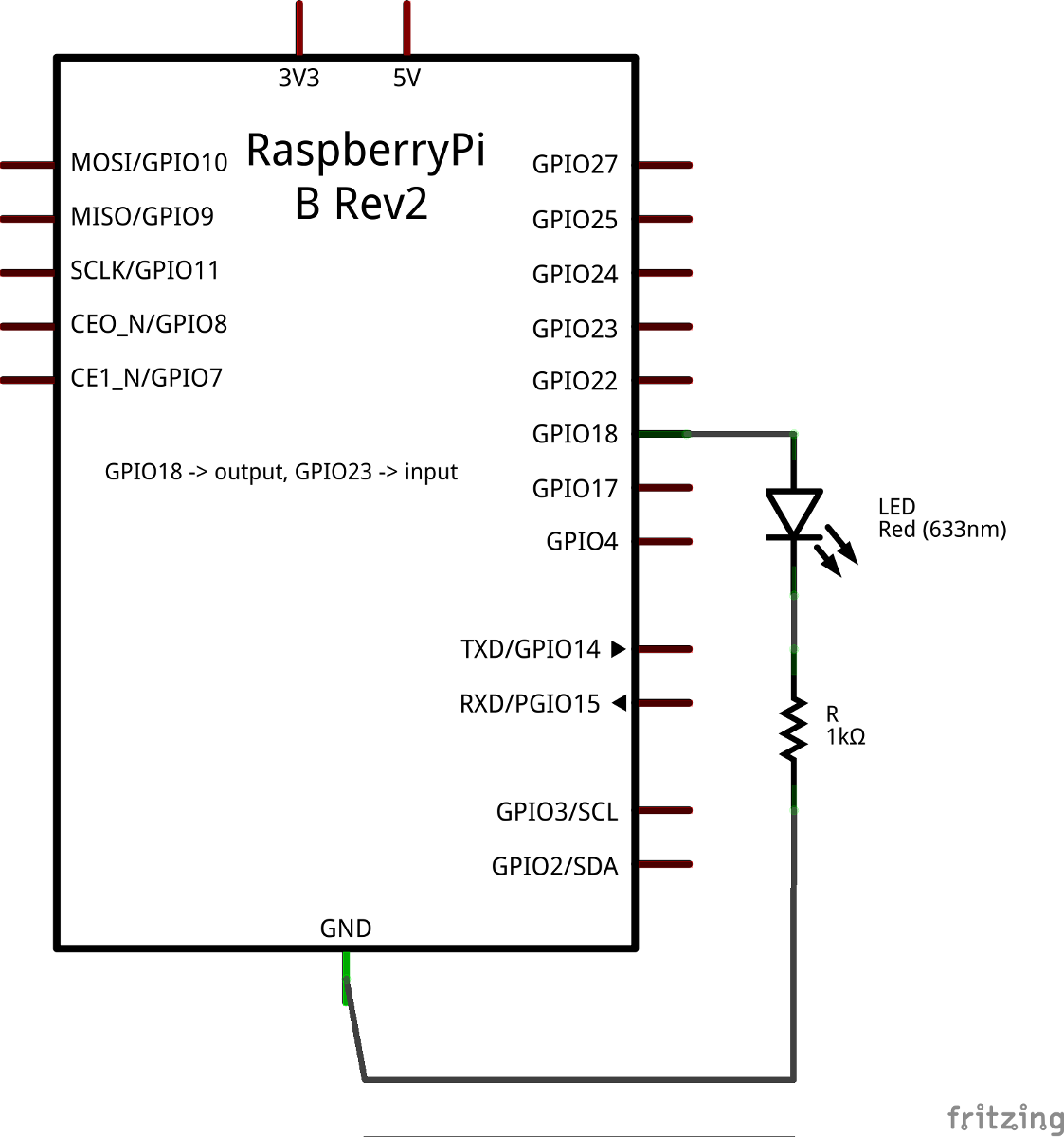
The following example will demonstrate how to make an LED blink at a periodic rate. The file led_blink.py contains the source code.
####1. Wiring It Up
The schematic below shows the wiring used for this particular example.
####2. Writing the Code
The first thing to do is to initialize the GPIO. The following code snippet shows how this is done for this particular example.
import RPi.GPIO as GPIO

def run():
    GPIO.setmode(GPIO.BCM)
    GPIO.setup(24, GPIO.OUT, initial=GPIO.LOW)
The call to GPIO.setmode() tells the Raspberry Pi how the pins are going to be referenced. It will either be set to GPIO.BCM (for BCM numbering) or GPIO.BOARD (for Board numbering). The GPIO.setup() function initializes a numbered pin as either input (GPIO.IN) or output (GPIO.OUT). It also allows an initial value for output pins to be set to either GPIO.LOW or GPIO.HIGH.
After the pin has been initialized it is ready to be used. The following code snippet expands on the previous one and demonstrates how this is done.
import rospy
import RPi.GPIO as GPIO

lit = False

def run():
    GPIO.setmode(GPIO.BCM)
    GPIO.setup(23, GPIO.OUT, initial=GPIO.LOW)

    rospy.init_node("led_blink", anonymous=False)
    rospy.Timer(rospy.Duration(1.0), timer_callback)
    rospy.spin()
GPIO.cleanup()

def timer_callback(event):
    global lit

    # Toggle the light state.
    lit = not lit
    if lit:
        GPIO.output(24, 1)
    else:
        GPIO.output(24, 0)
The rospy.Timer object is set to fire the timer_callback once per second. In this function the on/off state of the LED is toggled, which is accomplished with GPIO.output(). This function takes in a pin number and a 1 or 0 to indicate whether the pin is powered or not. The GPIO.cleanup() releases the setup for the pins.
####3. Running the Node
Now that the code is ready, make sure the command
$ source devel/setup.bash
has been run from inside the root of the workspace directory. Then run
$ rosrun rpi_examples_indigo led_blink.py
and watch the LED blink.
Note that an error may be thrown saying
RuntimeError: No access to /dev/mem. Try running as root!
If this occurs, simply run the command
$ sudo su
to become root and trying using rosrun again.
###Toggling an LED
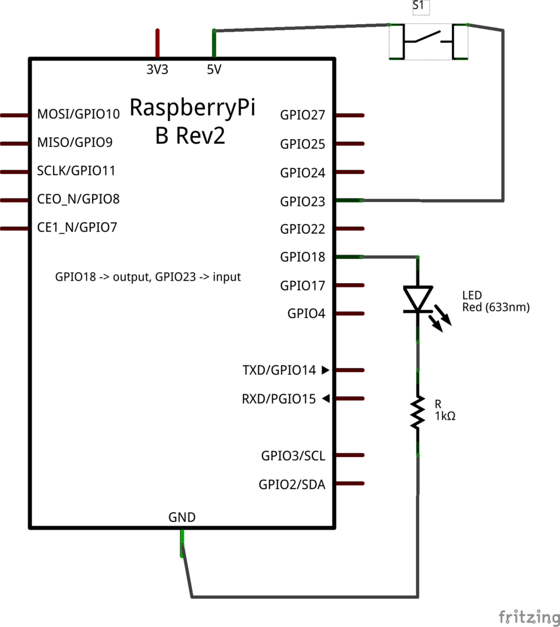
This example demonstrates how to take in a button press and use it to toggle the state of an LED. The full source code can be found in button_toggle_led.py.
####1. Wiring It Up
The schematic below shows the wiring used for this particular example.
####2. Writing the Code
The first thing to do is to initialize the GPIO. The following code snippet shows how this is done for this particular example.
import RPi.GPIO as GPIO

def run():
    GPIO.setmode(GPIO.BCM)
    GPIO.setup(18, GPIO.OUT, initial=GPIO.LOW)
    GPIO.setup(23, GPIO.IN)

    GPIO.add_event_detect(23, GPIO.RISING, callback=rising_edge_callback, bouncetime=400)
The initialization code in this example adds two additional lines of code compared to the prevoius example. The call
GPIO.setup(23, GPIO.IN)
initializes pin 23 to be an input. This is the pin that will take in the state of the pushbutton. The last line
GPIO.add_event_detect(23, GPIO.RISING, callback=rising_edge_callback, bouncetime=400)
sets up event detection based on the Raspberry Pi detecting a rising edge on pin 23, which will be generated by the pushbutton. The entry
callback=rising_edge_callback
specifies a callback function that will be fired when a rising edge occurs. The entry
bouncetime=400
provides some debouncing time to the entry to eliminate a flood of rising edge triggers.
Now that the code is initializing the pins and watching for a rising edge from the button it is time to make use of it. The following code snippet it puts it all together.
import rospy
import RPi.GPIO as GPIO

lit = False

def run():
    GPIO.setmode(GPIO.BCM)
    GPIO.setup(18, GPIO.OUT, initial=GPIO.LOW)
    GPIO.setup(23, GPIO.IN)

    rospy.init_node("button_toggle_led", anonymous=False)

    GPIO.add_event_detect(23, GPIO.RISING, callback=rising_edge_callback, bouncetime=400)

    rospy.spin()
    GPIO.cleanup()

def rising_edge_callback(channel):
    global lit

    lit = not lit
    if lit:
        GPIO.output(18, 1)
    else:
        GPIO.output(18, 0)
####3. Running the Node
Now that the code is ready, make sure the command
$ source devel/setup.bash
has been run from inside the root of the workspace directory. Also make sure roscore is running in another terminal. Then run
$ rosrun rpi_examples_indigo button_toggle_led.py
and use the pushbutton to make the LED toggle.
Note that an error may be thrown saying
RuntimeError: No access to /dev/mem. Try running as root!
If this occurs, simply run the command
$ sudo su
to become root and trying using rosrun again.

