-
Notifications
You must be signed in to change notification settings - Fork 3
IPEM Installation Quick Guide
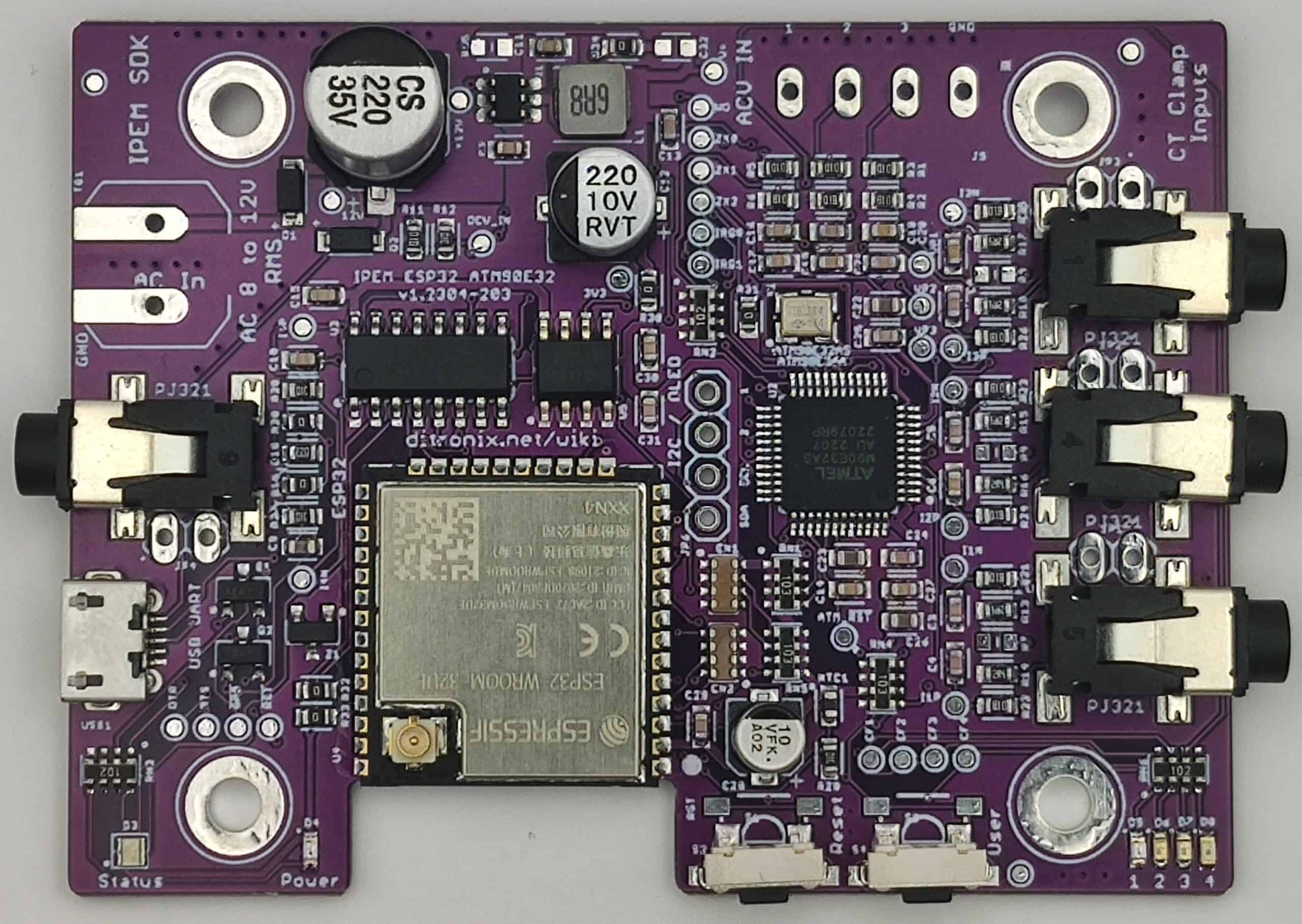
With the IPEM board in hand, you are not doubt eager to get it running, with minimal fuss or frustration - this quick guide will hopefully help.
-
Prerequisite. You will need to have PlatformIO installed.
- If you do not have PlatformIO installed
- Download and install official Free Microsoft Visual Studio Code
- PlatformIO IDE is built on top of VSCode
- Open VSCode Package Manager
- Search for the official PlatformIO IDE Extension
- Install PlatformIO IDE
- If you do not have PlatformIO installed
-
Initial Quick Check
- Connect a Micro USB cable to Computer and IPEM Board
- The IPEM board has bring-up code already on it - so you can just test.
- Open a Serial Monitor
- A quick option is ArduinoIDE, or load a project in PlatformIO and use this.
- Baud rate defaults to 115200
- Change Serial monitor Baud rate, if different.
- Press board Reset
- This should display various hardware information and default readings.
- The board is now ready for quick voltage and current testing, if you wished to do it now
- Press and hold USER button on board for ~ 1 second, to update Serial monitor readings
- If you have an OLED Display connected, this will update too.
*IPEM with OLED in the enclosure (available in our shop)
*
-
First Flashing
- Board already hardware configured for baseline use
- Board already software tested (using the below code)
- Download folder source code
- Open folder using PlatformIO
- Libraries should auto update as needed - saves hassle.
- Check code compiles without any errors
- Flash firmware via USB
- Check Serial Monitor
- This will display hardware information and default readings.
-
Initial Configuration
- Leave as defaults (for ATM90E32)
-
Setup WiFi
- Goto 'WiFi-OTA.h'
- Enter SSID / Password
- Static IP Required?
- Enter IP, or leave for DHCP
- Check WebServer
- Open Web Browser using board IP address
- Goto 'WiFi-OTA.h'
Web Browser Example Pages
-
Connect Mains transformer.
- Connect 12V AC, to board AC In.
- If only single voltage, connect V1, 2 and 3.
- Board will work OK without these connections but CT2 and CT3 Power Readings may not show.
- Reset board and check Voltage
- Connect CT Clamp(s)
- Reset board and check Power readings
The board is now ready.
Additional information, and other technical details on this project, maybe found in the related repository pages.
Repository Folders
- Code (Code examples for Arduino IDE and PlatformIO)
- Datasheets and Information (Component Datasheets, Schematics, Board Layouts, Photos, Technical Documentation)
- Certification (Related Repository Project or Part, Certification Information)
Repository Tabs
- Wiki (Related Repository Wiki pages and Technical User Information)
- Discussions (Related Repository User Discussion Forum)
- Issues (Related Repository Technical Issues and Fixes)
We value our Customers, Users of our designs and STEM Communities, all over the World . Should you have any other questions, or feedback to share to others, please feel free to:
- Visit the related Project plus the related Discussions and Wiki Pages. See tab in each separate repository.
- Project Community Information can be found at https://www.hackster.io/DitroniX
- DitroniX.net Website - Contact Us
- Twitter: https://twitter.com/DitroniX
- Supporting the STEM Projects - BuyMeACoffee
- LinkedIN: https://www.linkedin.com/in/g8puo/
Dave Williams, Eastbourne, UK.
Electronics Engineer | Software Developer | R&D Support | RF Engineering | Product Certification and Testing | STEM Ambassador
Supporting STEM Learning
Life is one long exciting learning curve, help others by setting the seed to knowledge.


