A Windows application for designing and simulating digital logic circuits. written in C++ using CMU graphics library.
- Overview
- How to Run
- User Manual
3.1 Add Component
3.2 Delete Component
3.3 Copy/Cut Component
3.4 Rename Component
3.5 Connect Components
3.6 Circuit Simulation
3.7 Save a Circuit
3.8 Load a Circuit - Issues
- Contributers
- License
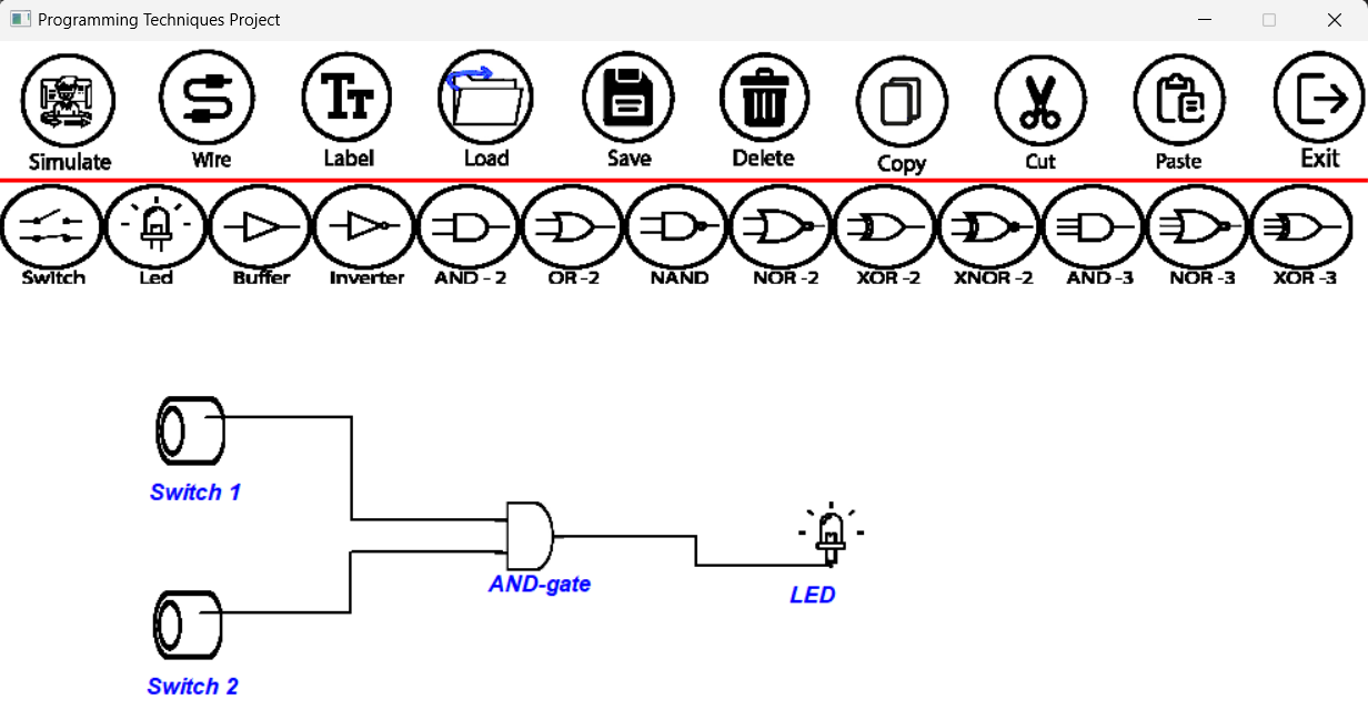
This application allows user to design and simulate digital circuits; to see its output and behaviour. Simulator provides a graphical user interface (GUI) with tools for drawing circuit diagrams, simulating logic functions, and analyzing the behavior of the circuit. This was the project of the first programming course in Cairo University, Computer Engineering Department.
- Download all files on your local machine.
- Open "Project Code Framework" folder.
- Open "graphics_prj.sln" file, using Visual Studio.
- Run the code (F5).
Makefile will be added soon.
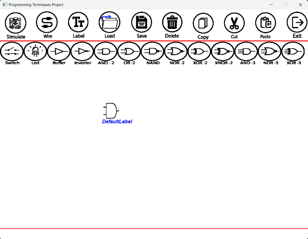
- From the toolbar click on the component you want to add.
- Click on the schema, wherever you want to place the component, the component will be added to the schema with "DefaultLabel".
- From the toolbar click on "Delete".
- Click on the component you want to delete.
- From the toolbar click on "Copy"/"Cut".
- Click on the component you want to "Copy"/"Cut".
- From the toolbar click on "Paste".
- Click on the schema, wherever you want to paste the component.
- From the toolbar click on "Label".
- Click on the component you want to rename.
- Write the new name, then press "Enter".
- From the toolbar click on "Wire".
- Click on the first end the the wire will be connected to.
- Click on the second end the the wire will be connected to.
- Wire will appear between the two ends.
- Build your digital circuit.
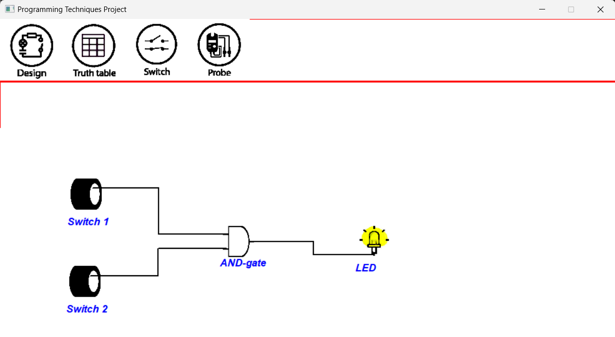
- From the toolbar click on "Simulate".
- To change the switch state (on/off), click on "Switch" from the toolbar then click on the switch.
- To return to the Design Mode, click on "Design" from the toolbar.
- From the toolbar click on "Save".
- Enter the file name to be saved, then press Enter.
- From the toolbar click on "Load".
- Enter the file name to be loaded, then press Enter. Make sure that the file is located inside "SavedFiles" directory.
- XOR gate is functioning like NOR gate.
- When switching to Simulate Mode, you should change the state of any switch to start the simulation. i.e simualtion does not start untill you change one of the switchs states.
- Deleting a wire is a little bit challenging.
- Truth Table and Probing is not implemtend.
Contributers in the project:
Copyright (c) [2021] [Ahmed Fathy, Khaled Mamdouh, Marwan Mostafa, Youssof Eldeeb]
Permission is hereby granted, free of charge, to any person obtaining a copy of this software and associated documentation files (the "Mars Exploration Simulator"), to deal in the Software without restriction, including without limitation the rights to use, copy, modify, merge, publish, distribute, sublicense, and/or sell copies of the Software, and to permit persons to whom the Software is furnished to do so, subject to the following conditions:
The above copyright notice and this permission notice shall be included in all copies or substantial portions of the Software.
THE SOFTWARE IS PROVIDED "AS IS", WITHOUT WARRANTY OF ANY KIND, EXPRESS OR IMPLIED, INCLUDING BUT NOT LIMITED TO THE WARRANTIES OF MERCHANTABILITY, FITNESS FOR A PARTICULAR PURPOSE AND NONINFRINGEMENT. IN NO EVENT SHALL THE AUTHORS OR COPYRIGHT HOLDERS BE LIABLE FOR ANY CLAIM, DAMAGES OR OTHER LIABILITY, WHETHER IN AN ACTION OF CONTRACT, TORT OR OTHERWISE, ARISING FROM, OUT OF OR IN CONNECTION WITH THE SOFTWARE OR THE USE OR OTHER DEALINGS IN THE SOFTWARE.


