-
Notifications
You must be signed in to change notification settings - Fork 9
Challenges strategies
Due to the heterogeneity in how NHPI MR scans are set up and acquired (as discussed above), NHP MR data can differ greatly in quality, orientation, size etc, across sessions and sites. This is one main reason why it is hard to develop the one single processing pipeline to process them all. Here we go through the typical challenges associated with NHP MRI data and the possible solutions we can take:
- Non-standard orientations
- Oblique datasets
- Non-head/brain components
- Image denoising
- Intensity bias correction
- Registration
- Brain extraction/Skull-stripping
- Segmentation
- Surface reconstruction
Typically, macaques are scanned in the sphinx position, which results in the acquired scans not conforming to the canonical orientation (standard human MRI orientation) that is expected in many standard neuroimaging packages.
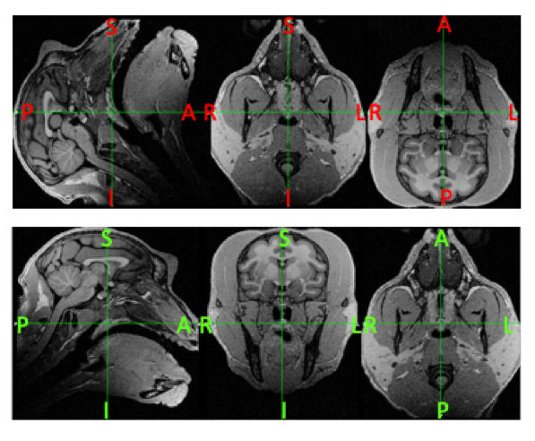
A check can be performed by loading your T1w or T2w image using a viewer e.g. fsleyes and take note of the orientation and axis labels. Examples of a bad (top) and good (bottom) oriented image in FSLeyes is shown below (Figure 5):
|
|---|
| Figure 5: Examples of a subject image that is in a non-canonical (Top) versus canonical orientation (Bottom). Take note that besides being in the wrong orientation, the axis labels in the top image are also incorrect. |
Automatic reorienting options include: the freesurfer command: mri_convert –sphinx; or the fsl command: fslreorient2std – which tries to orient the image match the standard template images (MNI152). Note that these tools might not necessarily work depending on the image. For instance, fslreorient2std requires the image orientation labels to be correct (not the case in the above example). Using these two commands in conjunction can be a solutions here, but always check your results.
Alternatively, one could also try a rigid-body alignment of the image to a template using the registration tools available in the various neuroimaging packages. The success of this alignment once again depends on whether your image is adequately “similar” to the template in terms of intensity values and field of view.
For a more hands-on option, you can use a combination of fslswapdim and fslreorient commands available in FSL to correctly swap the image axes, and correct the labels respectively (More info here: https://fsl.fmrib.ox.ac.uk/fsl/fslwiki/Orientation%20Explained).
For instance, in the example subject above, the automatic reorienting tools had not work, so I had to resort to the following commands using fslswapdim + fslorient:
fslswapdim ${name}_t1.nii.gz x z -y ${name}_t1_reorient.nii.gzfslorient -deleteorient ${name}_t1_reorient.nii.gzfslorient -setqformcode 1 ${name}_t1_reorient.nii.gz
Other potential tools for doing similar operations include AFNI’s 3drefit and Freesurfer’s mri_convert --in_orientation.
Other tools for manual and finer tuning of orientations include ITK-SNAP and the web-based Reorient tool (https://neuroanatomy.github.io/reorient).
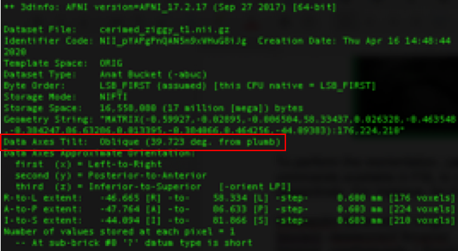
Sometimes MRI scans can be acquired in the oblique format in order to optimize the field of view. Using the 3dinfo command from AFNI, you can check if your data is oblique from the “Data Axes Tilt” field:
|
|---|
Figure 6: Output of 3dinfo showing the oblique-ness information in the image header. |
While some neuroimaging software takes into account this information found in the NIFTI header, others do not. This could lead to potential conflicts between inputs and outputs by mixing commands from different software under development.
One way to avoid this is to manually remove the “oblique” tag from the header using the AFNI command 3drefit -deoblique at the very start of the processing pipeline. Be very cautious to do this only when you are sure all your input images (T1, T2s) are acquired in the same format i.e. ALL oblique or ALL non-oblique.
If you prefer to keep your data in the native format (i.e. preserving the oblique tag), you have to make sure at every processing step, the output images have the same information conserved in the image header.
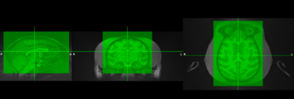
Typically, the NHP scans have a large FOV that contains the neck and other non-head parts. Cropping is important to reduce the extent of the image for more efficient and faster processing. Additionally, macaques have thick head muscles around the skull which sometimes can contain large signal biases that can complicate the registration and segmentation steps. Generally, we try to remove these effects by cropping the image prior to processing.
|
|---|
| Figure 7: Example of a typical cropping (green box) performed on a T1 image. |
An automatic cropping can be done with robustfov command in FSL. If it fails, the manual cropping can be manually performed via fslroi command in FSL: fslroi image.nii.gz image_cropped.nii.gz x +x y +y z +z, or interactively with the cropping option in FSLeyes. Other options include AFNI @clip_volume, FreeSurfer’s mri_convert --slice-crop. Be sure to keep track of your cropping values just in case you need to match your final processed images to the original uncropped image.
Due to the typically high spatial resolution of NHP images, they tend to have lower SNR. One way to increase SNR is to perform denoising on the images. For denoising, the adaptive non-local means denoising method (Manjon et al., 2010, J Magn Reson Imaging) is a suitable option due to the nature of NHP images (where noise is typically not equally distributed across the image). This denoising method is available in SPM (CAT12), ANTs (DenoiseImage), or downloadable as a Matlab package here.
If multiple structural images are acquired, averaging across them could be a good way to increase SNR. But it is advisable to first denoise each image first, and make sure the images are aligned (via eg. FSL Flirt or mri_motion_correct.fsl in Freesurfer) before performing the averaging.
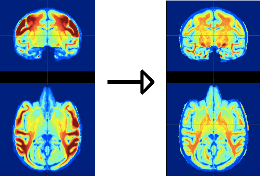
Intensity biases are a critical problem in NHP images because they impact many processing steps that rely on image intensities (for instance, image registration, segmentation and skull-stripping). As such bias-correction is a CRITICAL step in every NHP processing pipeline. An example of such bias is shown below. It is evident that this bias is due to the placement of coils at the sides of the head.
|
|---|
| Figure 8: Intensity bias correction in action: Left: skull-stripped T1w image displaying strong intensity bias due to the use of surface coil for MRI acquisition. Right: same image after bias correction using the T1wxT2w correction method (Rilling et al., 2011). |
There are many tools and techniques available for bias-correction. One popular tool is the N4BiasFieldCorrection program that is originally developed by Tustison et al.(2010, IEEE Trans Med Imaging) but available in many neuroimaging packages such as ANTs, MINC, etc). Other options for bias-correction include FSL-FAST and SPM’s bias correction program.
If T2 weighted scans are acquired from the same subject. One very powerful bias-correction method (see Rilling et al., 2011, Front Evol Neurosci.) can be applied. In this method , a bias-field is estimated via the square root of the product of the T1w and T2w images, smoothed, and then used to correct both the T1 and T2 images. We have found that this method, which is included in the HCP processing pipelines, works very well for high bias images like the one above.
Good image registration is core to many MR data processing steps and is very often and likely the key reason why your NHP processing pipeline fails on a certain image. As discussed earlier, NHP MR images typically suffer from low SNR, strong biases, non-standard orientations and have large FOVs (i.e. contain non-head/brain regions), which complicates the registration process as most registration tools (with their default parameters) “expects” clean, standardized images, more especially so if you are trying to register your image to a highly standardized template image. In other words, if all the above issues are minimized, there is a much higher chance that your registrations will work!
Among all the preprocessing steps above, skull-stripping is probably the most important one for registration. In humans, linear alignment is normally carried out on the skull-stripped input first to roughly align the brain to the template brain. Similarly, the optimal linear transform in NHP registration also requires a skull-stripped input to align with the template brain. Although the linear registration can be performed with head input to align with the template head, it might fail due to the quality of image (e.g. cropping, intensity correction). Hence, a fairly good skull-stripping image mostly guarantees the success of following non-linear registration (e.g., ANTs).
There are many tools available in the various neuroimaging software packages for linear and non-linear image registrations. These registration programs usually have many parameters that you can tweak to optimize your registrations.
For the less savvy, there are existing registration scripts that have been tailored to deal with NHP (macaque) image registrations. One good example is the NMT_subject_align.sh script that is available with the NMT macaque template release(Seidlitz et al., 2017, Neuroimage). This script computes registrations (both linear and nonlinear), using a series of AFNI commands, between your input image and a template (default=NMT template, but you can use your own preferred one). Again, to ensure the success of this script, it is important that your input NHP MR image has been properly bias-corrected, cropped and denoised, and to resemble the template you are using as much as possible (e.g. when using a skull-stripped template, use a skull-stripped input).
7. Brain Extraction/Skull-stripping
There are two main approaches to extracting the brain (or skull-strip) NHP MR structural images: 1) Template-based - that involves first transforming the subject image to a template (or vice-versa), and then using the template brain mask to extract the brain from the subject image; or 2) Non template-based (Intensity based) - that generates a brain mask via an algorithm that starts off with an initial brain mask (or sphere) and gradually expanding it till it reaches the skull/non-skull boundary (e.g. FSL-BET); 3) Deep learning approach such as convolutional neural network.
Common tools for template-based brain extraction, among many others, include AntsBrainExtraction (ANTs), and AtlasBrex. Note that the AtlasBrex tool actually starts off with an initial brain mask computed via a non-template based method (FSL-BET) and then attempts to adjust this mask based on linear and non-linear registrations to a template brain mask. For these tools to work well, it is important to have well-standardized input structural images (i.e. cropped, denoised, bias-corrected, correctly oriented), that are as similar to the template as possible, to facilitate the template-subject registration that is core to template-based skull-stripping methods.
With regards to non template-based tools, FSL’s BET tool emerges as one of the most popular tools with many useful parameters to optimize your brain extraction process . Some general tips include 1) having a properly standardized input image, 2) indicating the correct center coordinates of the brain in the (-c) parameter and the correct head radius in the (-r) parameter, 3) playing around with the -f and -g parameters to obtain the best mask from your image. An alternative is to use Lennart Verhagen’s ‘bet_macaque’ wrapper around BET that is part of Mr Cat toolbox. This effectively implements an iterative version of BET, focusing separately on the middle of the brain, the temporal poles, and the frontal pole and then combines the result.
To overcome the challenges of skull-stripping in MRI, researchers have started to seek solutions using deep learning methods. A growing number of studies have demonstrated the feasibility of convolutional neural networks (CNN) in human MRI. In NHP, one example is the transferring U-Net Model that has been initially trained in the human dataset and upgraded with a NHP sample. Given that notable variations in data quality across sites in NHP, the model allows further upgrade with a small amount of sample (n<=2) to achieve a decent skull-stripping results Find the method here.
Of course, most of the time, we would not be able to get the perfect brain mask from our NHP images. Typically, parts of the brain near the frontal pole, tips of the temporal pole and the occipital ends might be missing due to signal dropouts or biases. Brain masks can be manually corrected via tools such as ITK-SNAP, and BrainBox.
As with brain extraction, brain segmentation (i.e. segmenting the anatomical image into the main tissue types: gray, white matter and CSF) can be performed via template-based (e.g. SPM’s Segment Tool, ANTs’ Atropos and AntsAtroposN4, FSL-FAST, etc.) or non template-based methods (FSL-FAST).
The same lessons hold as with brain extraction : For optimal segmentation using template-based methods, the appropriate template must be used and the input image must be as similar to the template brain (and its tissue segmentations) as possible in terms of intensity contrasts, orientation, and size to facilitate registration. For non template-based methods, which is highly dependent on intensity contrasts to determine tissue segmentation, intensity biases must be minimized in the input images.
Lastly, to obtain the perfect tissue segmentations, you can opt to perform manual corrections on your segmentations yourself using e.g. ITK-SNAP, Slicer, or collaboratively via the web-based BrainBox tool.
Automatic surface reconstruction is a challenging task in NHP given that the default parameters in most of the toolboxes are designed for human data. It heavily relies on the quality of denoising, intensity bias correction, brain extraction, segmentation of gray matter and white matter, as well as registration. To date, there are several surface pipelines for NHP data emerging and more coming together (e.g. HCP-style NHP pipeline, Precon_all, CIVET-Macaque, NHP-Freesurfer, etc.).
Here we take FreeSurfer as an example to demonstrate common challenges and potential solutions in this step:
-
“Fake” the voxel size: By default, FreeSurfer converts the input T1w image for surface reconstruction to 256x256x256 dimension at 1 mm resolution. This often works for human data since 1 mm is the common resolution of human T1w image. Given the small brain in NHP, the voxel size of high-resolution T1w is usually less than 1mm (e.g. 0.5 mm in macaque). If the original voxel size is kept, the conforming in FreeSurfer would downsample the high-resolution input to a low-resolution image. To avoid this processing, we need to change the unit of voxel size in the header of the input image. For example, 0.5 mm resolution of macaque data can be changed to 1 mm in the header (i.e.
pixdim) as if the voxel size is 1 mm. In this way, we ‘cheat’ FreeSurfer ‘conform’ step and keep the high-resolution input untouched. Note that the surface reconstructed based on the ‘size-fake’ input will be magnified. After the surface reconstruction, a scaling factor needs to be applied to the surface mesh to match the original volume images. -
Intensity Normalization: The surface reconstruction in FreeSurfer is mainly based on the image intensity (white matter: ~100-110, gray matter: <100). Besides the prior intensity bias correction, FreeSurfer processing steps (command:
mri_nu_correct.mni,mri_normalize) are recommended to normalize white matter and gray matter to the above range. Manual correction of this step is provided in FreeSurfer using control points (https://surfer.nmr.mgh.harvard.edu/fswiki/FsTutorial/ControlPoints_freeview). -
White Surface reconstruction: The accuracy of white matter segmentation determines the quality of white surface. When the intensity normalization succeeds (i.e. white matter intensity is ~100-110), the white matter segmentation (command:
mri_segment) in FreeSurfer is generally well. The failed case can also be corrected by setting control points in FreeView. Users can also implement good segmentation from other packages into FreeSurfer by naming the white matter mask as ‘mri/filled.mgz’. Note that the size of filled.mgz is most likely magnified. Any segmentation in the original space without FreeSurfer needs to be converted in the similar way into FreeSurfer. Next, users can separate the left and right hemispheres using commandmri_pretessand tessellate the white matter to create the surface mesh for each hemisphere bymri_tessellate. After generating the initial white surfaces, smooth, inflating and topology fixing steps are followed. In order to obtain the topologically correct surface (i.e. topologically homeomorphic to a sphere), the small holes inside or ‘spikey’ boundary of the white matter segmentation mask needs to be filled or cleaned up. -
Pial surface reconstruction: The pial surface reconstruction in FreeSurfer is mainly determined by the intensity of the input. FreeSurfer searches the voxels with lower intensity outwards from the white matter surface and recognizes them as gray matter. The inhomogeneity or noise (e.g. image artifacts) has a substantial impact in this step. The good segmentation from other packages or manually corrected mask needs to be prepared as an ‘aseg’ file in FreeSurfer. An alternative intervention is to use the gray matter mask to re-normalize the intensity of the brain image. After that, a pial surface along cortical thickness measures can be created using
mris_make_surfaces.
A. Why the interest in NHP neuroimaging?
B. What makes NHP MRI challenging?
C. Typical data analysis challenges
D. Structural data processing steps and PRIME-RE tools
E. Functional data processing steps and PRIME-RE tools
F. Diffusion data processing steps and PRIME-RE tools
G. Cross-species comparisons and PRIME-RE tools


