-
Notifications
You must be signed in to change notification settings - Fork 0
PORT_C
PORT: The C Program
I've programmed the "Hello, World" for embedded projects: A blinking LED.
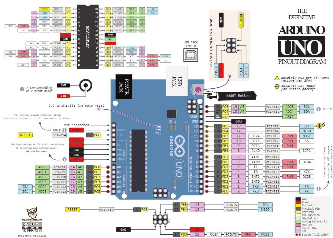
As you can see, it is pretty straightforward. If you know how to do it. Because I am using the Arduino UNO development board, I am making Digital Pin 13 of that board blink. Why? Because that's where this development board has a LED built in.
Now, how do you make Digital Pin 13 blink? All I see in the code below is just some DDRB, PORTB and a 5. There are valuable resources online available, which I highly recommend to Programmers who want to use the extra speed of manipulating Registers directly:
There, you can see that Digital Pin 13 is using PB5, which is PORTB 5. Now, to make the LED on that Pin blink, you need to manipulate the DDRB and PORTB registers as shown below. And voila! There you have your blinking LED. Hello World!
#include <avr/io.h>
#include <util/delay.h>

int main() {
	DDRB |= (1<<5);

	while(1) {
		PORTB ^= (1<<5);
		_delay_ms(500);
	}
}
If you don't know what any of that means, look at the documented code in this repository. I've explained every line of code there! 😃
This all compiles to 162 Bytes of Flash and 0 Bytes of RAM.
Ok, this is kinda scary, but let's do it. I got the assembly out of a .lss file which gets generated after compiling the program.
80:	sbi	0x04, 5			; 4
82:	ldi	r25, 0x20		; 32
84:	in	r24, 0x05		; 5
86:	eor	r24, r25
88:	out	0x05, r24		; 5
8a:	ldi	r18, 0xFF		; 255
8c:	ldi	r19, 0x69		; 105
8e:	ldi	r24, 0x18		; 24
90:	subi	r18, 0x01	; 1
92:	sbci	r19, 0x00	; 0
94:	sbci	r24, 0x00	; 0
96:	brne	.-8      	; 0x90 <main+0x10>
98:	rjmp	.+0      	; 0x9a <main+0x1a>
9a:	nop
9c:	rjmp	.-26     	; 0x84 <main+0x4>
Remember, the Datasheet is your best friend when dealing with embedded programs. If we don't know what sbi means for example, we just look it up.
So, let's step through this line by line.
80: sbi 0x04, 5 ; 4
The sbi command is short for Set bit in I/O register. As parameters, it takes the adress offset for the IO-Register and which bit it should set in that register.
So, sbi 0x04, 5 sets the 5th bit in the I/O register with the offset 0x04. If you look at the Register Summary of the Datasheet, offset 0x04 is the DDRB register. Compare that with the code line DDRB |= (1<<5). Basically, it is the same!
We just understood our first line of assembly! Really nice! So let's move on to the next one:
82: ldi r25, 0x20 ; 32
Let's see if we can find what ldi stands for. According to the Datasheet: Load immediate.
All this command does is just loading the value 0x20 (which is 32 in decimal aka. 2^5 aka. (1<<5)) into r25 (which I think is register 25, just some register we can write stuff to and then we can read out of that register at a later point).
What secrets does the next line contain?
84: in r24, 0x05 ; 5
The in command. What does it mean? The wisdom of the Datasheet strikes again: In port.
Basically, we store the contents of the I/O register at offset 0x05 in register r24. So we take the contents of the PORTB register (offset 0x05) and write them into r25.
What do we do now? Let's find out:
86: eor r24, r25
It's getting harder and harder coming up with good transitions. So let's look what the Datasheet has to offer for eor: Exclusive OR registers.
Basically, it just performs an exclusive or (X-OR) on the two given registers. So we X-OR the contents of PORTB (r24) with 0x20 (r25) and stores the result in r24.
Last but not least:
88: out 0x05, r24 ; 5
out is the opposite of in: It takes the contents of r24 and writes it back to the I/O register with the adress offset 0x05 aka. PORTB.
Remember the last time I mentioned our C code? Well, now it is time we mention it again. All of this assembler code:
82:	ldi	r25, 0x20		; 32
84:	in	r24, 0x05		; 5
86:	eor	r24, r25
88:	out	0x05, r24		; 5
Is the equivalent of:
PORTB ^= (1<<5);In C++.
I won't go through each line of assembler now, but I will share the important facts about the next bit:
8a:	ldi	r18, 0xFF		; 255
8c:	ldi	r19, 0x69		; 105
8e:	ldi	r24, 0x18		; 24
90:	subi	r18, 0x01	; 1
92:	sbci	r19, 0x00	; 0
94:	sbci	r24, 0x00	; 0
96:	brne	.-8      	; 0x90 <main+0x10>
98:	rjmp	.+0      	; 0x9a <main+0x1a>
9a:	nop
9c:	rjmp	.-26     	; 0x84 <main+0x4>
All of those instructions are the compiled version of _delay_ms(500). We already know the ldi instruction from above. If you're interested in the other instructions, then go ahead and look it up in the Datasheet.
After the delay of 500ms, the instruction at adress 9c gets executed. We jump back up to adress 84 after the 500ms passed.
Basically, this is the while(1) portion of our program.
And that's all there is to it! The "Hello, World!" of the embedded world, in assembler.
You might think now: "Good ting that we have C. It takes care of all that assembler stuff for us."
And you are totally right. Now, the C code is kinda confusing too. You need to know everything about the registers and so on. And that's why I am developing a C++ library. To make the code easier to write, less error prone and make it more readable. And if I can do that with zero overhead, that's another cherry on top.
After reading the Datasheet in preperation for the ZOL version of this program, I discovered that toggling
a pin can be achieved by writing a 1 to the corresponding bit in the PINx register. This results in this C code:
#include <avr/io.h>
#include <util/delay.h>

int main() {
	DDRB |= (1<<5);

	while(1) {
		PINB |= (1<<5);
		_delay_ms(500);
	}
}
Which gets compiled to this assembly:
80: sbi	0x04, 5			; 4
82: sbi	0x03, 5			; 3
84: ldi	r18, 0xFF		; 255
86: ldi	r24, 0x69		; 105
88: ldi	r25, 0x18		; 24
8a: subi	r18, 0x01	; 1
8c: sbci	r24, 0x00	; 0
8e: sbci	r25, 0x00	; 0
90: brne	.-8      	; 0x8a <main+0xa>
92: rjmp	.+0      	; 0x94 <main+0x14>
94: nop
96: rjmp	.-22     	; 0x82 <main+0x2>
If you compare this assembly to the assembly above, we can identify the _delay_ms(500) portion of the assembly pretty easy. So our "real program" are just the two sbi instructions at adress 80 and 82.
Amazing, isn't it?
What do we learn from this? Well, read the Datasheet before you want to write fast performing code. Or create a GitHub repository in which you describe how you develop ZOLs, tell the reader to read the Datasheet and then read the Datasheet yourself during the process of writing a Wiki entry. 😇