-
Notifications
You must be signed in to change notification settings - Fork 5
sweep
The <sweep> operator is similar to linear/rotate extrude as it extends a 2d shape into a solid, but <sweep> is more general as it uses a cubic spline curve, with options to control the orientation and scale of the swept profile along the curve.
Limitation: The swept body is not allowed to self-intersect in any way, implying that the sweep curve must not define a closed loop. If self-intersection occurs for any reason, the outcome is undefined.
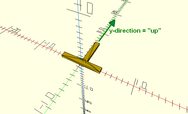
Given the above, the sweep feature can be introduced by first considering an ordinary <linear_extrude> of a profile assembled from 2 rectangles, in order to define the profile orientation used in sweeping:
<?xml version="1.0" encoding="utf-8"?>
<xcsg version="1.0">
    <metadata>
        <software name="angelcad" version="v1.0-01"/>
        <model name="sweep1" created="2017-05-25T09:27:55"/>
    </metadata>
    <linear_extrude dz="0.5">
        <union2d>
            <rectangle dx="8" dy="1" center="true"/>
            <rectangle dx="1" dy="6" center="false"/>
        </union2d>
    </linear_extrude>
</xcsg>
The 2d profile is created in the xy-plane and extruded slightly in z-direction, to illustrate the profile.

In <sweep>, the 2d y-direction is considered the profile "up" direction. For any position on the sweep curve, the profile plane is oriented normal to the curve tangent and the profile "up" direction is guided by the sweep curve "up" vector (vx,vy,vz).
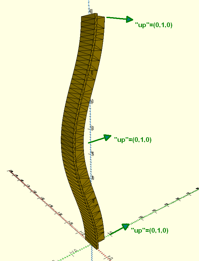
To sweep the profile above, <linear_extrude> is replaced by <sweep> containing a <spline_path>. The path is a cubic spline curve defined using (x,y,z) coordinates and (vx,vy,vz) "up" vectors in each control point. In the example below, the coordinates define a non-straight curve and the "up" vectors are all constant unit-length vectors (vx,vy,vz)=(0,1,0):
<xcsg version="1.0">
   <metadata>
      <software name="angelcad" version="v1.0-01"/>
      <model name="sweep1" created="2017-05-25T09:50:43"/>
   </metadata>
   <sweep>
      <union2d>
         <rectangle dx="8" dy="1" center="true"/>
         <rectangle dx="1" dy="6" center="false"/>
      </union2d>
      <spline_path>
         <cpoint x="0" y="0" z="0" vx="0" vy="1" vz="0"/>
         <cpoint x="0" y="-1.1697778701782227" z="10" vx="0" vy="1" vz="0"/>
         <cpoint x="0" y="-4.1317596435546875" z="20" vx="0" vy="1" vz="0"/>
         <cpoint x="0" y="-7.5000000000000000" z="30" vx="0" vy="1" vz="0"/>
         <cpoint x="0" y="-9.6984634399414062" z="40" vx="0" vy="1" vz="0"/>
         <cpoint x="0" y="-9.6984634399414062" z="50" vx="0" vy="1" vz="0"/>
         <cpoint x="0" y="-7.4999995231628418" z="60" vx="0" vy="1" vz="0"/>
         <cpoint x="0" y="-4.1317596435546875" z="70" vx="0" vy="1" vz="0"/>
         <cpoint x="0" y="-1.1697769165039062" z="80" vx="0" vy="1" vz="0"/>
         <cpoint x="0" y="0" z="90" vx="0" vy="1" vz="0"/>
      </spline_path>
   </sweep>
</xcsg>
The result is a solid with the expected shape:

This can be brought one step further by gradually modifying the profile orientation so that the top end is rotated e.g. 45 degrees relative to the start at bottom. At the same time the length of the profile up-vector is gradually scaled down by to reach a factor 0.25 at the top, relative to the starting unit vector. The result is a more complex solid (numbers below have been edited for clarity of presentation):
<?xml version="1.0" encoding="utf-8"?>
<xcsg version="1.0">
   <metadata>
      <software name="angelcad" version="v1.0-01"/>
      <model name="sweep1" created="2017-05-25T10:45:38"/>
   </metadata>
   <sweep>
      <union2d>
         <rectangle dx="8" dy="1" center="true"/>
         <rectangle dx="1" dy="6" center="false"/>
      </union2d>
      <spline_path>
         <cpoint x="0" y="0.00000000000" z="0"  vx="0.00000000000" vy="1.00000000000" vz="0"/>
         <cpoint x="0" y="-1.1697778701" z="10" vx="0.07580491592" vy="0.86829236882" vz="0"/>
         <cpoint x="0" y="-4.1317596435" z="20" vx="0.12910480707" vy="0.73845768497" vz="0"/>
         <cpoint x="0" y="-7.5000000000" z="30" vx="0.16176190227" vy="0.61550483107" vz="0"/>
         <cpoint x="0" y="-9.6984634399" z="40" vx="0.17713541457" vy="0.50394897739" vz="0"/>
         <cpoint x="0" y="-9.6984634399" z="50" vx="0.17980998235" vy="0.40759259560" vz="0"/>
         <cpoint x="0" y="-7.4999995231" z="60" vx="0.17524045705" vy="0.32934432720" vz="0"/>
         <cpoint x="0" y="-4.1317596435" z="70" vx="0.16933726672" vy="0.27108540825" vz="0"/>
         <cpoint x="0" y="-1.1697769165" z="80" vx="0.16802092313" vy="0.23359034089" vz="0"/>
         <cpoint x="0" y="0.00000000000" z="90" vx="0.17677669227" vy="0.21650634706" vz="0"/>
      </spline_path>
   </sweep>
</xcsg>
The solid follows the original curve, but has varying profile scale and orientation:

Generally, any 2d shape that can be subject to linear/rotate extrude may also be subject to the <sweep> operator. The 2d shape profile may for example contain holes.