-
Notifications
You must be signed in to change notification settings - Fork 5
Principle_Task_Design
ArControl use the State Machine principle in order to construct sequential procedures of a task diagram. A task schedule can be homogeneously decomposed as a sequence of States, where each State playes a relevant role within the task.
ArControl enables a schedule to be graphically programmed by assigning elements into box-frames, rather than by textual scripts.
The State is a stand-alone object defining “do something for outputs,” “detect triggers,” and subsequently “respond to a trigger by switching to a corresponding next-State”.

(A) The State has a do-function to deliver stimulus, and when-functions that master the transitions cross States. (B) Component and Session structures are the primary and the secondary collection of States.
-
State Output (
doPin, do-function ): Each State could proactively activate a specific output channel (OUT1-8) to present the animal with a stimulus (denoted as do-pin).- Turning a channel on/off for once.
- Keeping a channel on for a specified time
-
State Transition: It specifies when the current State should be exited (when-function), and which corresponding State should be subsequently entered (transition-function).
-
whenCountworks when the current State’s entry has been counted for the specified number of times. -
whenPinworks when a desired input channel (IN1-6) is activated. -
whenTimeis the maximum survival time of the State, if none of the previous conditions were activated. - When the current State matched the conditions above, transition-function makes transition to the next State, next Component or Session Exit. There was only one State running at any moment.
-
-
State, Component and Session: The
Component(abbr. C) is a virtual collection ofState(abbr. S) that benefited the States arrangement. In the same way, the Components formes theSession, which is a technical term that representes the schedule and the task.- The entry of a task (
Session) is State-1 from Component-1 (C1S1). - The entry of a
Componentis its' own State-1 (C*S1). - The exit of a
Sessionis State-0 or Component-0 (C*S0,C0,C0S0).
- The entry of a task (
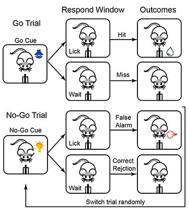
Take the demo Go/No-Go task for example.

Schedule of the Go/No-Go task.
Firstly, this task schedule can be homogeneously translated into a sequence of States, by State Machine principle.

Illustration of a Go Trial in the Go/No-Go task.
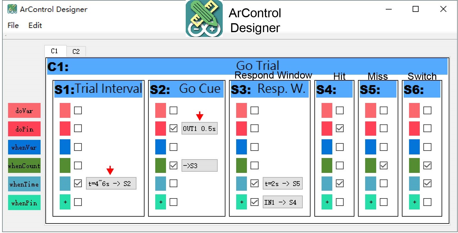
Then, use ArControl Designer to compose these State. The main layout itself intuitively mimickes the diagram of the State Notation modeling. Different States can be added and deleted in the GUI. Further details of a State are configured through several pop-up windows.

Main window of the ArControl Designer shows an implementation of the Go/No-Go task.