Assemble Sensor IO Housing
The sensor IO housing consists of three Arduino Uno boards, two CAN-BUS Shield boards and two sensor IO boards.
- 14” length of 1” - Self-wrapping sleeving
- 18" long 20 AWG insulated copper wire (white)
- 18" long 20 AWG insulated copper wire (red)
- 18" long 20 AWG insulated copper wire (purple)
- 18" long 20 AWG insulated copper wire (blue)
- 18" long 20 AWG insulated copper wire (brown)
- 18" long 20 AWG insulated copper wire (green)
- 18" long 20 AWG insulated copper wire (grey)
- 18" long 20 AWG insulated copper wire (yellow)
- Three 18" long 20 AWG insulated copper wire (black)
- 4" long 20 AWG insulated copper wire (black)
- 4" long 20 AWG insulated copper wire (red)
- 5" long 20 AWG insulated copper wire (black)
- 5" long 20 AWG insulated copper wire (red)
- 10" long 20 AWG insulated copper wire (black)
- 10" long 20 AWG insulated copper wire (red)
- 24" long 20 AWG insulated copper wire (black)
- 24" long 20 AWG insulated copper wire (red)
- 18" long twisted pair 20 AWG insulated copper wire (blue/orange)
- 4" long twisted pair 20 AWG insulated copper wire (blue/orange)
- 6" long twisted pair 20 AWG insulated copper wire (blue/orange)
-
Print the enclosure if you haven't yet.
-
Create twisted pair if you haven’t yet
-
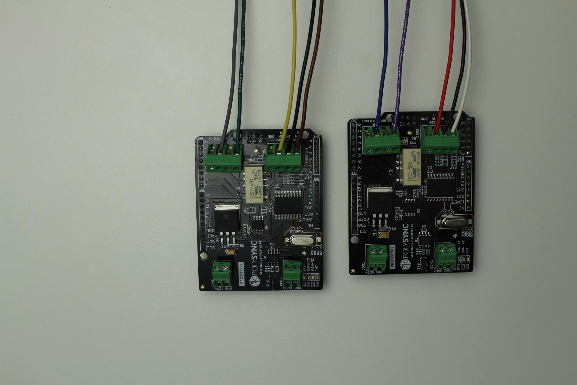
Connect The ten 18” wires to the sensor IO boards
- Wire color locations are documented in the overview drawing in Appendix 1. Refer to the OSCC Steering Module and OSCC Throttle Module.

- Wire color locations are documented in the overview drawing in Appendix 1. Refer to the OSCC Steering Module and OSCC Throttle Module.
-
Test fit Arduino Uno to the sensor IO board. You will need to do this after the Arduino Uno boards are screwed into the sensor IO housing.

-
Screw in the three arduino Uno boards to the housing
-
Connect the two CAN-BUS boards together

-
Attach the sensor IO boards to the outer Arduino Uno boards. The CAN-BUS boards to the middle Arduino Uno board.
-
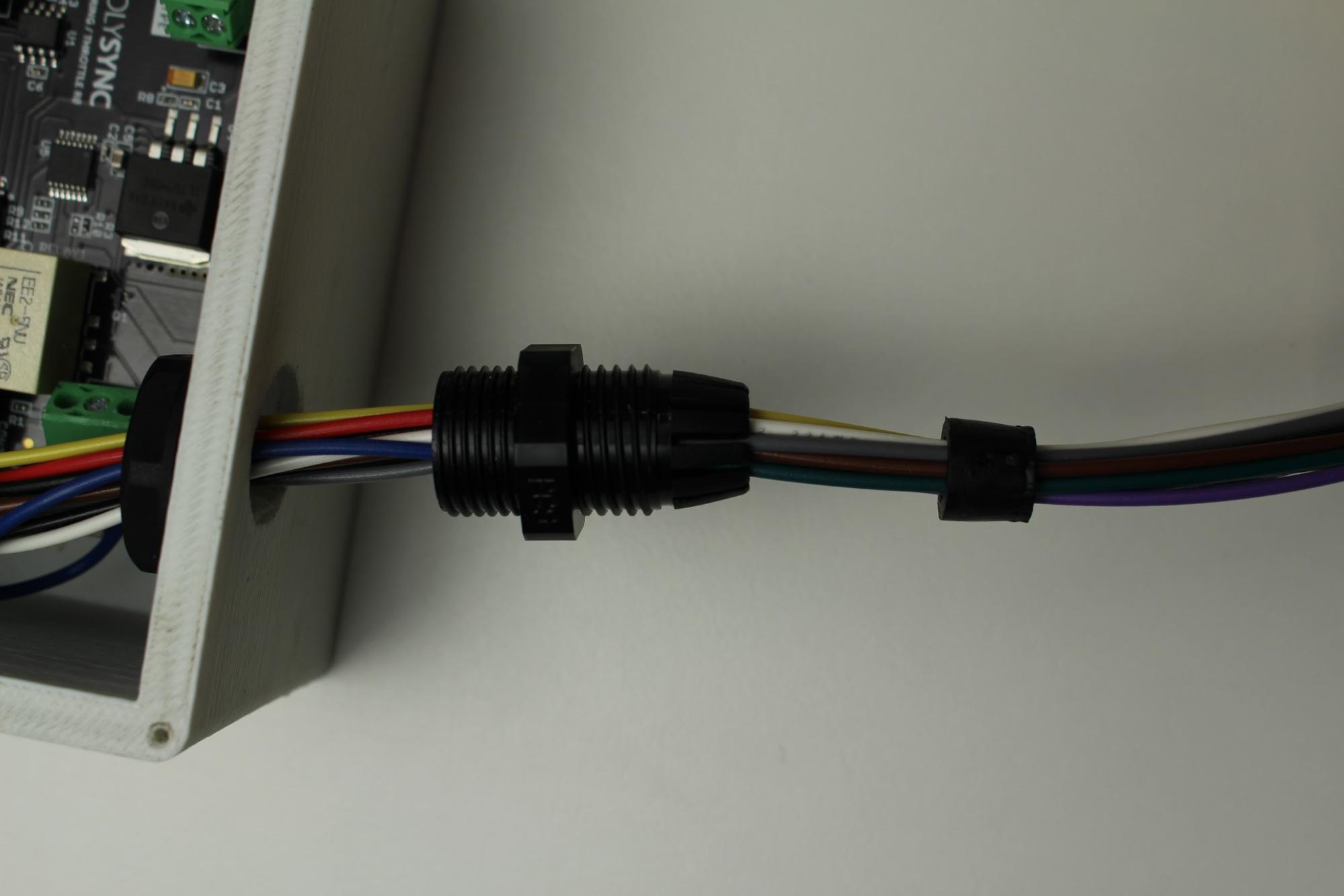
Route 18” of twisted pair and the 24” lengths of Red and Black wire through the round opening of the sensor IO housing.
-
Affix the wire grommet to the sensor IO housing

-
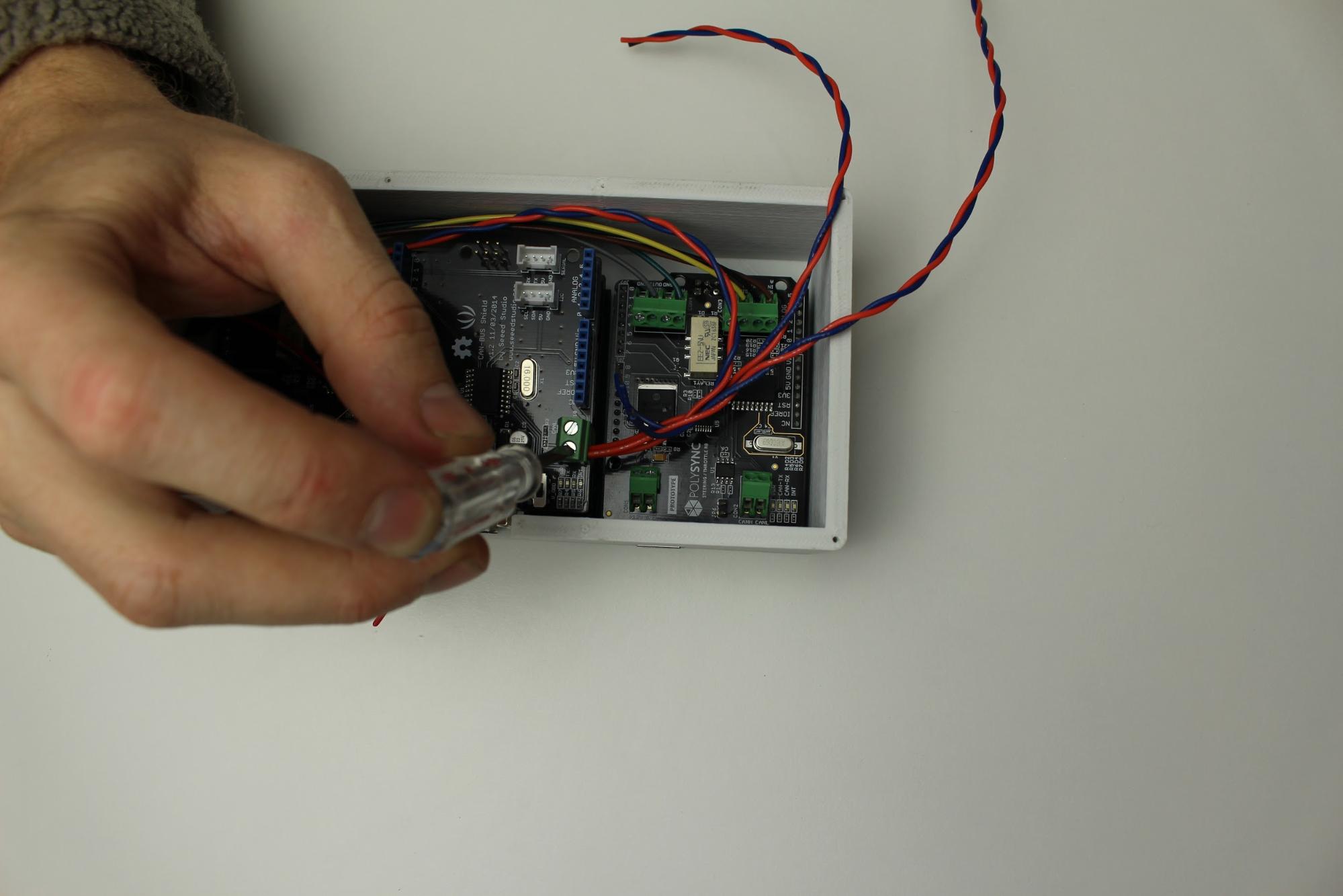
Using the 4” and 6” twisted pair connect the CAN-BUS to the sensor IO boards. Use the overview drawing in Appendix 1 to wire the OSCC CAN Gateway, OSCC Steering Module and OSCC Throttle Module

-
The red circles are the locations of the power connections to the sensor IO and CAN-BUS boards. Refer to drawing in Appendix 1.

-
Butt splice the power wires together as shown above. Use heat shrink tubing for insulation.

-
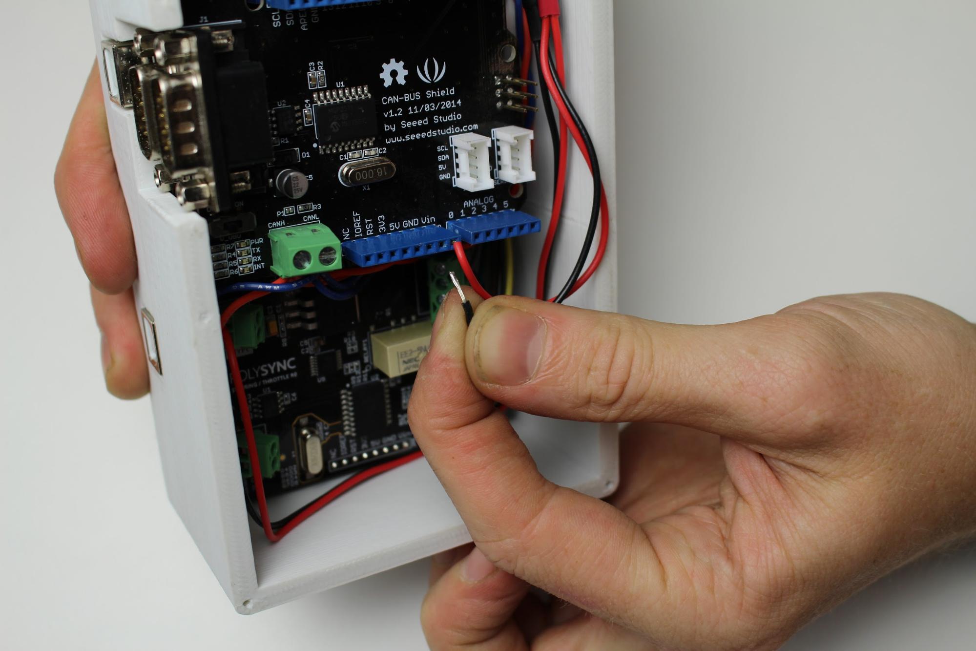
Connecting the power wires to the sensor IO boards.

-
Tin the wires that will be connected to the CAN-BUS boards, connect them to the top CAN-BUS board.


-
Connect the Deutsch connectors, you should hear a clicking sound when the wire is securely in the Deutsch connector.
-
Create bypass terminator to verify splicing was done correctly
