-
Notifications
You must be signed in to change notification settings - Fork 2
userguide
There are three on and off states for the display: the power supply switch, the on/off switch on the back of the display, and the graceful shutdown (a combination of the power supply switch and on/off switch). This section explains the need for each On/Off switch state and how to use them.
The power supply switch provides power to the display. The power supply rocker switch is located on the wire cord near the USB-C port.
TURNING ON the power supply powers the micro-controllers and servos on the back of the display. When the display is first powered up, and when the main controller (Raspberry Pi Pico-W) is configured to connect to your WIFI, the main controller starts the display startup sequence as displayed by its LEDs. See the table in the Quick Start Guide found in the section Kinetic Display Controls Settings Admin Page.
TURNING OFF the power supply while the display is showing time, date, temperature, or humidity, results in the display segments remaining extended. Do not try to physically push the segments back into the display while the display is powered off as it could damage the servo and components in the back of the display. Note when the power to the display is turned off or cut off, the display internally stores its last known state and will resume when the power supply switch is turned back on.
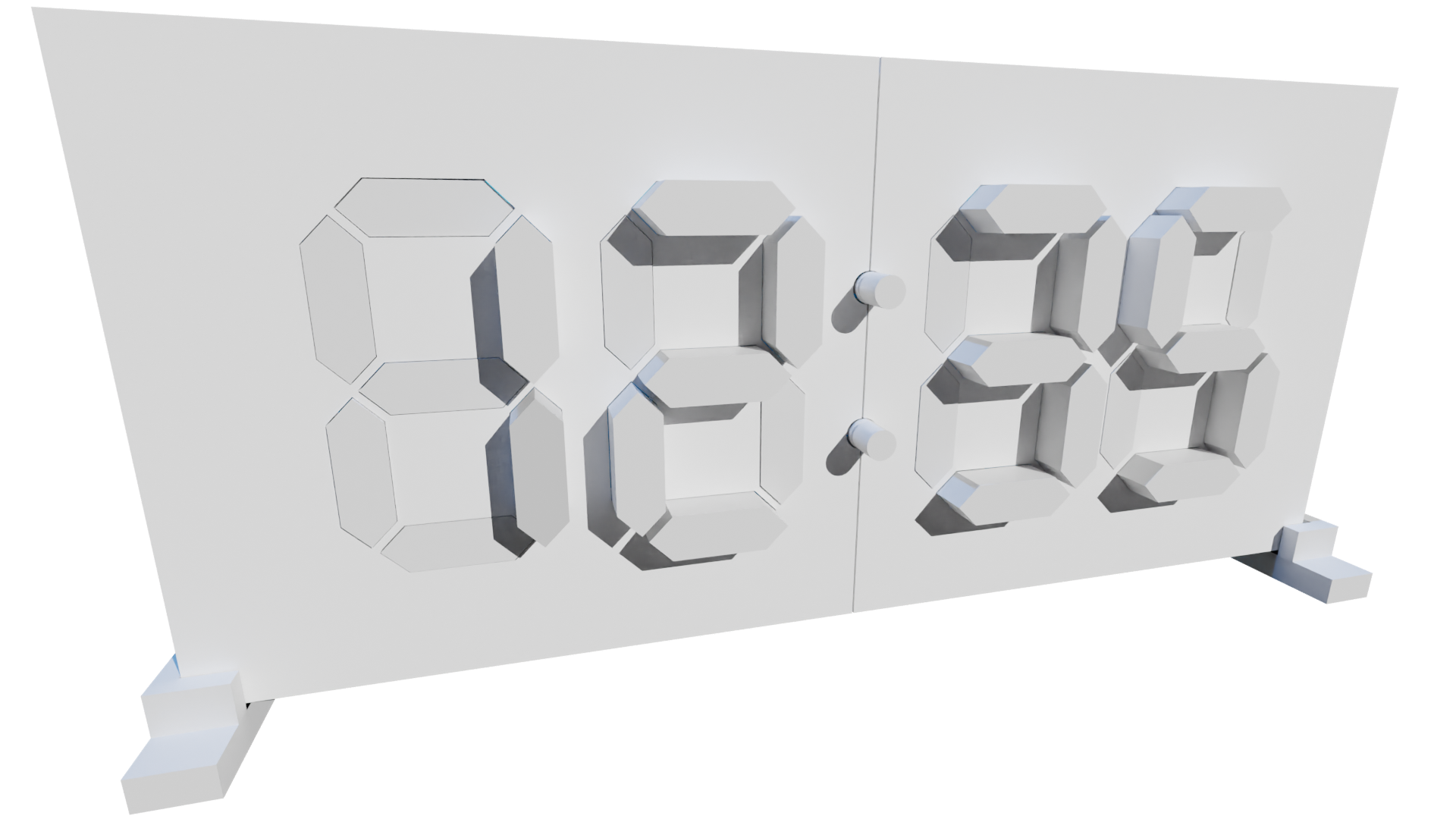
The on/off switch on the back of the display only works when the power supply switch is turned on.
TURNING OFF the back-of-display switch causes all extended segments to retract, then hibernates the micro-controllers in the display to a low power consumption mode.
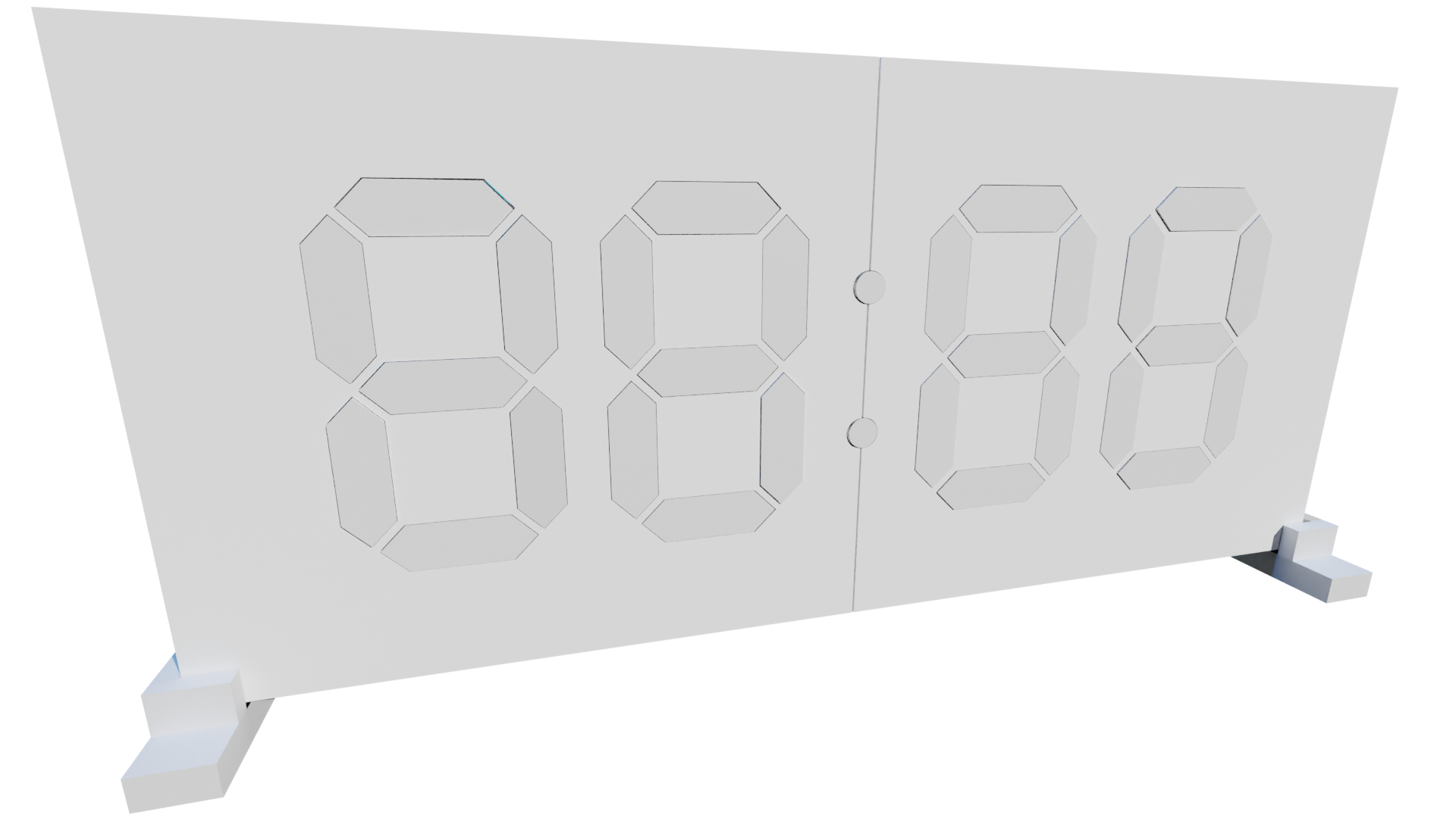
TURNING ON the back-of-display switch resumes the rotating displays. Note there may be a delay of up to 15 seconds as the micro-controllers wake up every 15 seconds to check the status of the on/off back of the display switch.
Graceful shutdown of the display begins by TURNING OFF the back-of-display switch which causes all the extended segments to retract. Next, TURNING OFF the power supply gracefully shuts off your display. This sequence ensures there are no extended segments while the display is powered off.
Accessing the Kinetic Display Control Settings begins when the display has no power and TURNING OFF the back-of-display switch. Next, TURNING ON the power supply switch turns on the display’s WIFI hotspot and results in the RED and GREEN LEDs simultaneously turned on. See the Display Controls Settings Admin Page in the Quick Start Guide on how to access the page from your phone, laptop, or computer.
Behind the display face is a sg90 mini servo motor that extends and retracts its segment. These inexpensive servos are used in remote controlled toys such as cars, airplanes, or robots. Over time the servo wears down causing the segment to not retract all the way into the display face or extend out as far as the other segments. Therefore, you’ll need to make slight adjustments to keep the segments aligned.
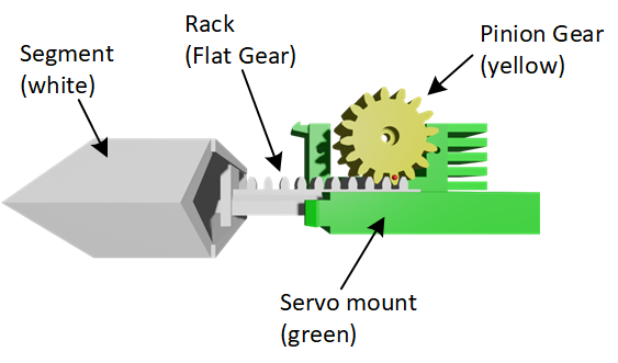
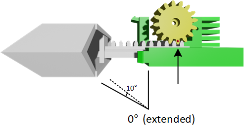
The illustration below is a top view of a few of the basic components in the rack and pinion segment assembly. The segment is a white hexagonal top and rack (flat gear). The servo is mounted on two screws onto the green servo mount. The yellow pinion gear is mounted on the servo.
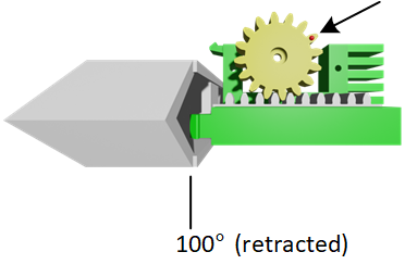
When first installed, the servo is set to 100° and the pinion gear is positioned to have the segment’s rack retracted into the display face, see the figure below. Note the position of the pinion gear tooth marked with a red dot.
-
Disconnect the UART Tx and Rx connections to the pair of digits that you will NOT be adjusting. For example, remove the UART Tx and Rx connections to Digit 2 and 3 when changing Digit 0 or 1 settings.
-
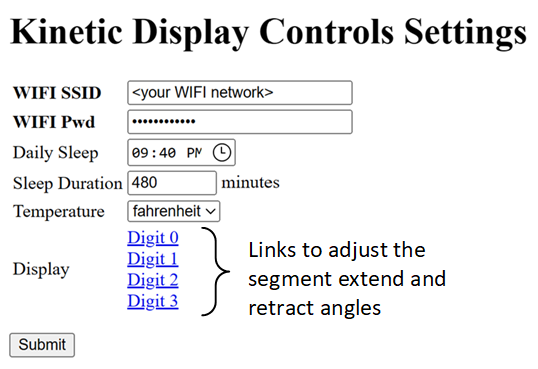
Click on a link to Digit 0 – 3 from the Kinetic Display Control Settings Admin Page, see figure below.
-
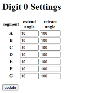
Set one or more of the extend or retract angles for each segment A-G, see figure below.
-
Click the “update” button. Note that each segment will extend in order from A-G using your new setting. After all the segments have been extended, they retract in order from A-G.
-
Repeat the process until all the adjustments have been made.
-
Reconnect the UART Tx and Rx connections.