-
Notifications
You must be signed in to change notification settings - Fork 1
Components
This page outlines the components of the BEVO Beacon that are not the sensors. For information regarding the sensors, check out the Sensors page.
![]()
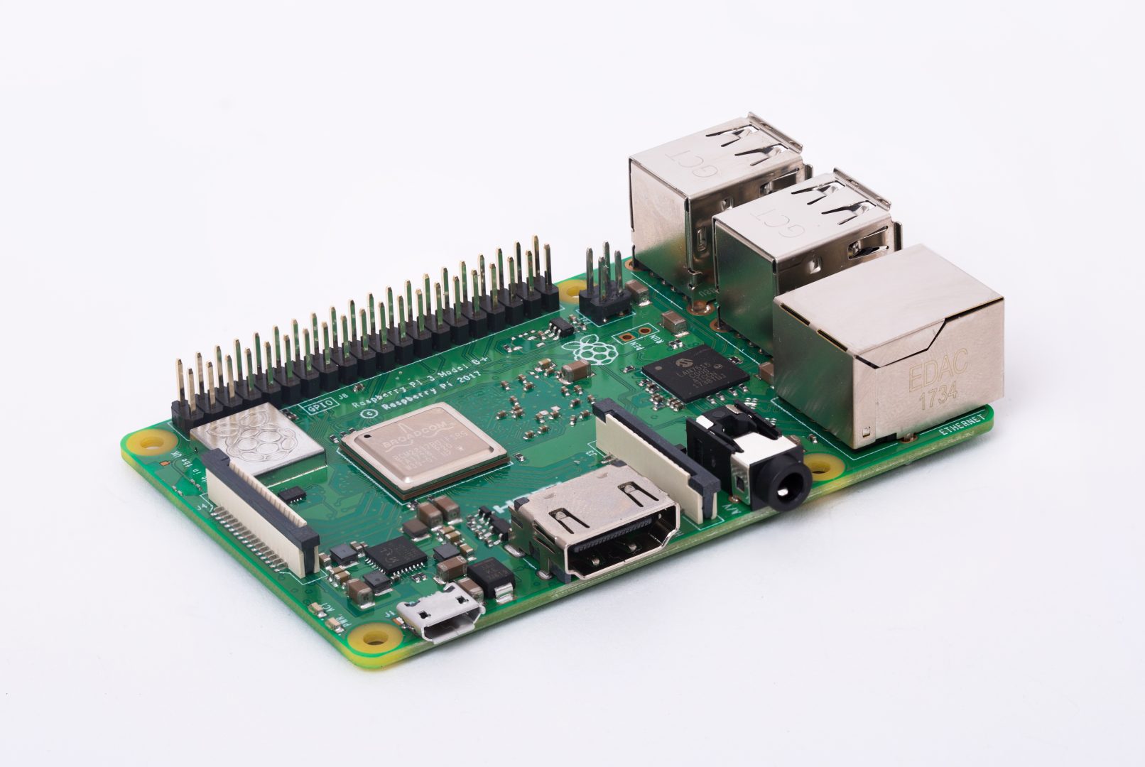
The puppeteer pulling the string on the BEVO Beacon: a single board computer that powers and communicates with the other components. The RPi 3|B+ was originally chosen because it comes with built-in WiFi capabilities, Bluetooth, inter-integrated communication protocol, and 4 USB-A ports.

The OS can be found on Raspberry Pi's website here. There are multiple options, but we opt for the Raspberry Pi OS Lite (new or legacy versions) which utilizes a no-nonsense, command line interface.
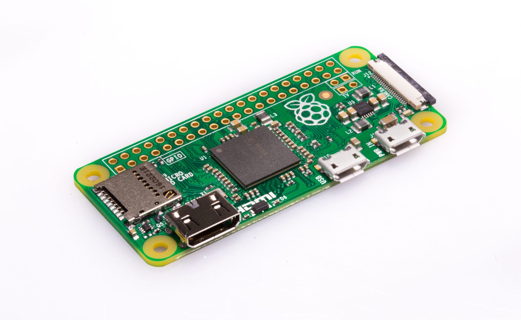
Some versions of our device forego the use of the 3|B+ in favor of the Zero W which is a more compact version that does not include any standard size USB-A ports but an extra micro-USB port alongside the one used to power the device. By using the Zero W, we save space and reduce the heat generated within the device at the cost of only slightly slower processing speeds and the removal of one of the USB-A connected sensors (typically the NO2 sensor)

To ensure that exact time is kept when the device is disconnected from WiFi, we include a Real-Time Clock (RTC) developed by Adafruit -- the PCF8523. The sensor is shown below with clearly labeled connections. We do not use the square-wave (SQW) pin, but connect the remaining four.
The OLED display that cycles through the different measurements made by all of the sensors - we use the SSD1306. The module with the labeled connections is shown below. From left to right (based on the image), those connections are GND, VCC, SCL, and SDA.
We include a small (30 mm X 30 mm) cooling fan to help with heat management by blowing air across the RPi and perpendicular to the compartment within the BEVO Beacon that houses the sensors. This fan has two pins that simply plug into any of the VCC (3.3V or 5V) and GND pins on the RPi.

We developed a printed circuit board (PCB) for this project to allow for easier setup and a more professional look. We highlight the older and final versions of the PCB that was developed.
The original design we simplistic, lining up all the same connections vertically. Using only sensors with inter-integrated communication protocol gave us the ability to simplify the PCB and the connections between pins.
From left to right, the connections on the PCB are:
Ground (GND1) - Black
GND2 - Black
VDC - Red
Serial Data (SDA)- Yellow
Serial Clock (SCL) - Green
Connections for two 4.7 k-Ohm resistors are given at the top and below the RTC connection for the pull-up resistors for the SDA and SCL.
We solder male headers to each of the sensor connection locations which are then connected via varying length wires. We also solder the resistors directly to the board. This version of the PCB did not include connections for the OLED screen nor the fan which were instead wired directly to pins on the RPi.
The project the BEVO Beacon was originally developed for grew and more was required on the BEVO Beacon which forced us to develop a new PCB that could handle all the components. We also wanted to create a PCB that fit like a hat on the RPi rather than "float" in the device. Developed by UT ECE student Angelina Ibarra, the final version of the PCB is shown below:
![]()
This version includes bottom-mounted female headers which fit directly to the male headers on all RPis. All the original connections are included in addition to extra for the fan and OLED screen in addition to connections for the possibility of including a microphone and AlphaSense NO2 sensor. We also include a surface-mounted LED which indicates the WiFi connection status of the device (see Auxiliary Programs page for more details).
More questions that can be answered here? Contact the creator, Hagen Fritz, at [email protected]