-
Notifications
You must be signed in to change notification settings - Fork 28
Debugging hints
Even though the ZY12PDN board has SWD pads on the back side, debugging is limited.
The reason is that the same microcontroller pin is used for both SWDIO and the FUSB302 interrupt line. The firmware has been designed such that the interrupt line is not used until a USB PD power source has been detected. So uploading firmware and debugging the startup is possible. But once a USB PD source has been detected, the interrupt line is configured and the debug port no longer works (until the next restart).
Using the build flag -D PD_DEBUG, debugging output can be enabled. The baud rate is 115,200 bps (8 bits, 1 stop bit, no parity).
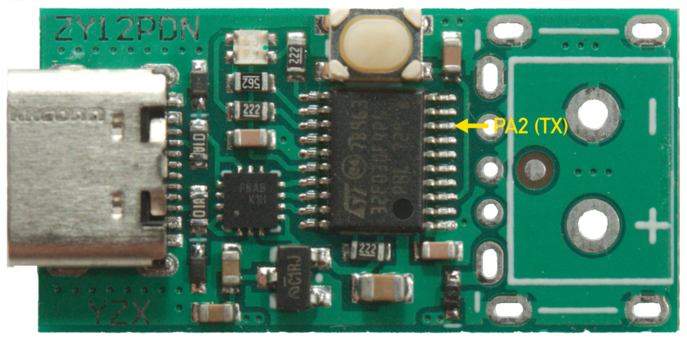
The serial output is available on pin PA2 on the microcontroller. To connect a serial adapter, a wire needs to be soldered to it. Given the microcontroller's small pitch, it requires good soldering skills.

Since the USB PD protocol is timing sensitive, debug output must not delay normal operation. For that reason, the debug output is written to a circular buffer and then transmitted using non-blocking DMA. Blocking UART operation would introduce delays and violate the timing causing the power supply to reset or even to cut power.