Simple DC Motor Servo using Arduino
Building very, very, very large RC Servo
Standard PPM signal (like classic RC Servo)
- D1 Output of servo tester or RC reciever
Driving signal for H-Bridge
- D9 - PWM output
- D6 - direction Left
- D7 - direction Right
Rotary Potentiometr
- A1 - signal from rotary potentiometer
ch1_interrupt is called when state of reciever input is changed. Than pulse width is measured. That value is mapped to input value of P controller. That P controller works output mapped to PWM generator and two direction output. Those outputs are controlling motor H-Bridge IC (like VNH 5019)
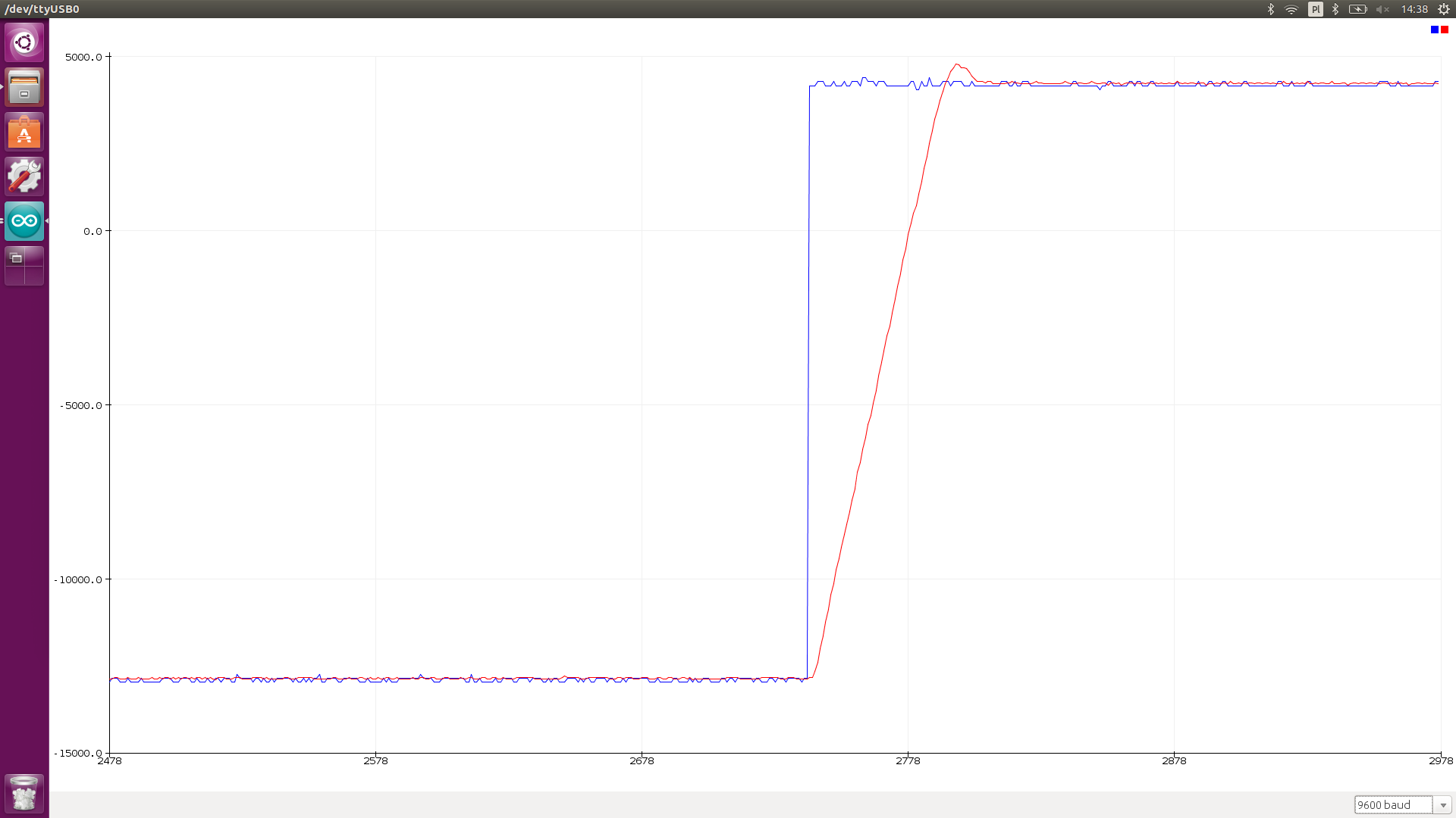
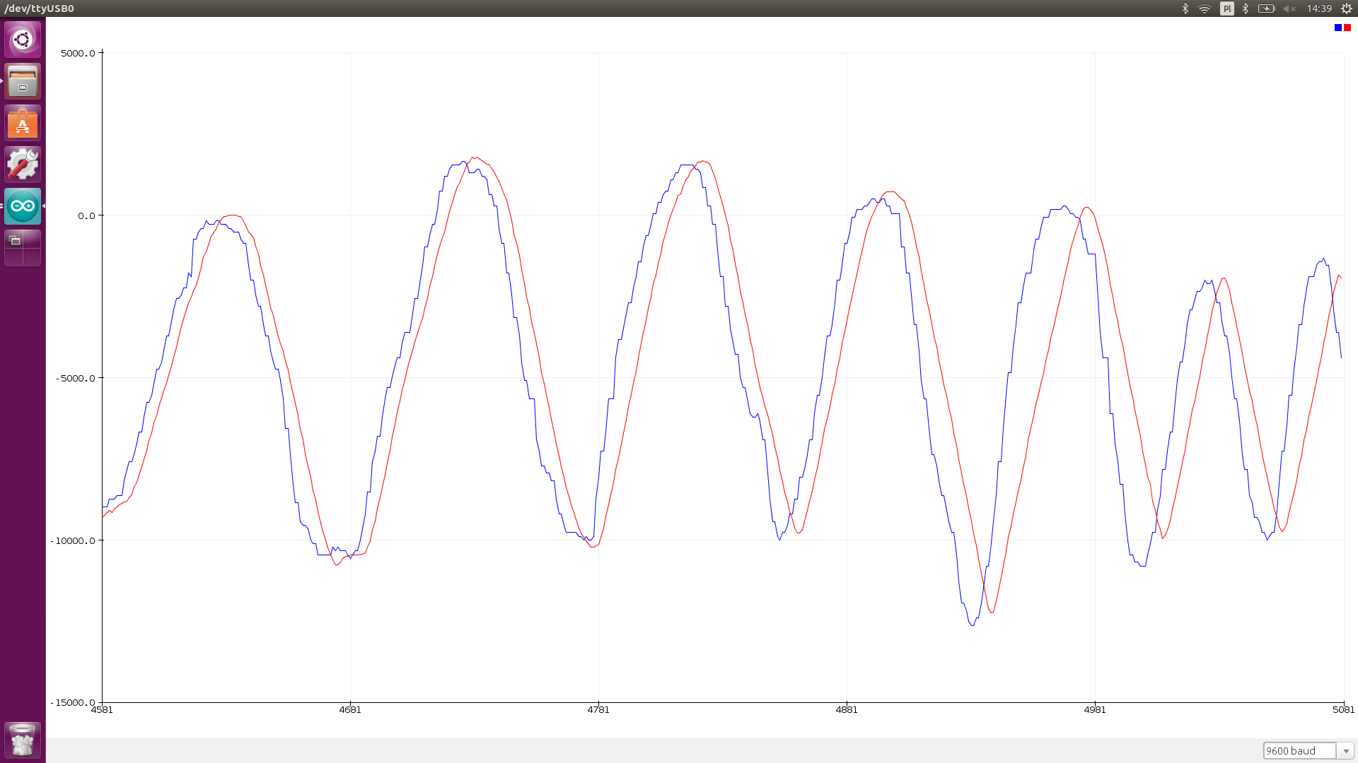
Arduino sends over port control setpoint and measurment. Thus it can be plotted.
If you experience constant movement, please check if feedback (rotary potentiometer is connected in right direction).
- Support for multiple RC channels (max 2), maybe SBUS
- Digital outputs


