The robin flight software supports the MAV_CMD_PREFLIGHT_CALIBRATION command, and will issue instructions through the STATUSTEXT messages for the user to follow. It is recommended that you leave the flight controller on for ~5 minutes to allow all of the components to heat up, as IMU temperature compensation is currently not implemented. It should also be noted that to ensure correct procedure, only 1 calibration can be performed at a time.
If using QGCS, the custom interface can be used to issue the corresponding commands. It is recommended that you open the notices menu so you can easily see the calibration instructions.
If using MAVROS, you should be able to use the following process to perform a calibration. It is recommended that you open the command interface so you can easily see the calibration instructions.
To perform a gyroscope calibration:
- Place the autopilot on a flat surface
- Do not bump the device then issue the calibration command:
- MAVROS:
rosrun mavros mavcmd long 241 1 0 0 0 0 0 0 - QGCS Widget: Press
Send gyroscope calibration command
- MAVROS:
- The calibration should only take a few seconds
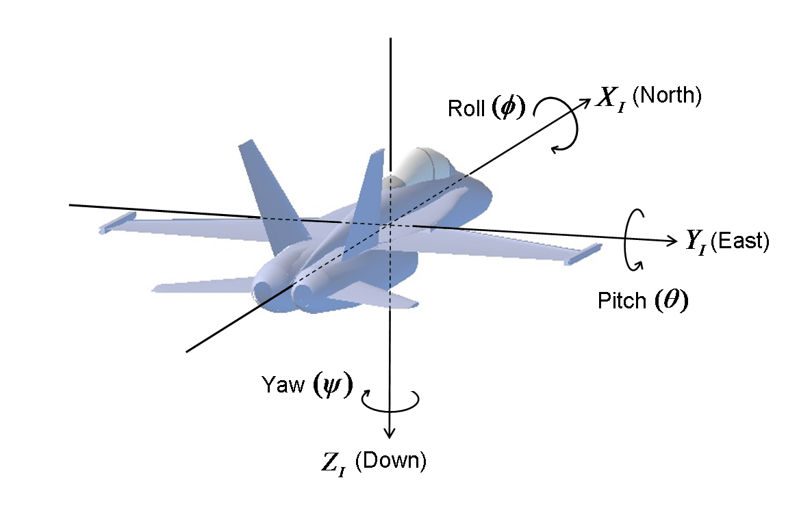
The flight controller uses the NED frame of reference. During the calibration steps you will be instructed to orient each axis of the flight controller, with the axis oriented both pointing up to the sky and pointing down to the ground.
To perform a accelerometer calibration:
- Place the autopilot on a flat surface, with the Z-axis pointing down (in the NED frame)
- Hold the device steady, then issue the calibration command:
- MAVROS:
rosrun mavros mavcmd long 241 0 0 0 0 1 0 0 - QGCS Widget: Press
Send accelerometer calibration command
- MAVROS:
- Repeat step 2, following the instructions sent back from the autopilot
- The calibration should only take a few seconds per axis, but it will need to be done for each axis, in both directions
Before performing a radio control calibration, you must first connect a PPM compatible RC reciever. For the complete calibtation, you should also set the parameters RC_MAP_ROLL, RC_MAP_PITCH, RC_MAP_YAW, and RC_MAP_THROTTLE before proceding.
To perform an RC calibration:
- Ensure RC transmitter and reciever are bound and ready. Send the initial RC calibration command:
- MAVROS:
rosrun mavros mavcmd long 241 0 0 0 1 0 0 0 - QGCS Widget: Press
Send RC calibration command
- MAVROS:
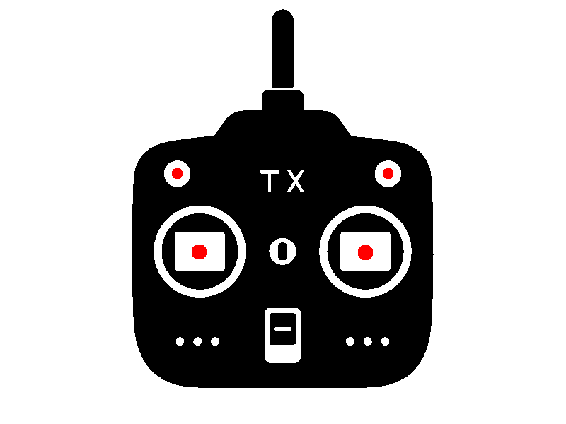
- Set RC to stick centered, then reissue the calibration command.
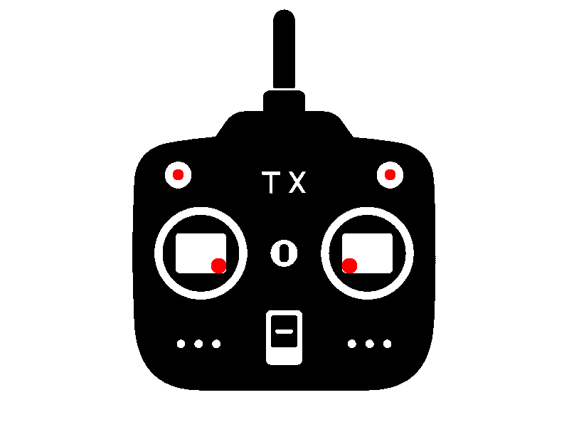
- Set RC to lower inner corners, then reissue the calibration command.
-
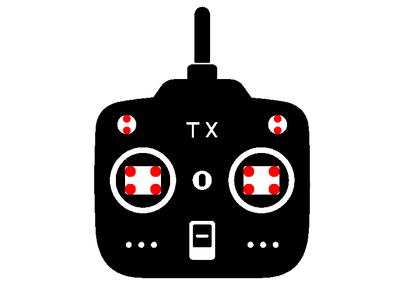
Move all sticks and switches to extremes, then reissue the calibration command when done.
-
Calibration should now be complete.
Battery monitoring can be performed in two steps.
- Enable monitoring by setting the number of cells of your battery with the
BATT_N_CELLSparameter (currently only supports LIPO batteries). - Attached the battery voltage to the
VBATTpins on the flight controller
Note: The flight controllers are not protected from reverse polarity across the VBATT port (as it is much higher than the operating voltage). Connecting this port backwards will destroy your flight controller. It is highly recommended that you makke this connection in a manner that cannot be accidentally reversed (i.e. solder wires directly from your PDB to the appropriate pints on the flight controller.
Once configured and connected, you can adjust your battery readout, and the various feedback warnings via the other BATT_* parameters (see the parameter reference for more details.
An ESC calibration can be performed to ensure that the ESCs are correctly informed on the throttle PWM ranges (i.e. so they know what is 0% and 100%).
Note: Some older ESCs may not respond well to the "common" method of performing an ESC calibration. DO NOT PERFORM THIS PROCESS WITH PROPELLERS ATTACHED! Refer to you your ESC manual if the process is not successful to find an alternative method of calibration.
The following process should be taken to perform an ESC calibration:
- Connect via telemetry
- Ensure the motor map is set correctly and your motors are wired correctly.
- Set the
DO_ESC_CALparameter to "true"/"1", then write parameters to ensure this setting is saved for your next boot. - Disconnect all power to your system.
- Power on the flight controller and all ESCs at the same time (usually this means that you need to connect the battery).
- Automatic ESC calibration will begin.
PWM_MAXis applied to all mapped ESCs for 2 seconds, heartbeat led will flash rapidly.PWM_MINis applied to all mapped ESCs to signal calibration complete (ESCs should make some form of confirmation tone).DO_ESC_CALparameter is automatically turned off and saved to ensure calibration is not performed on next boot.
- Wait 10 seconds to ensure ESCs have saved their calibration.
- Disconnect and reconned all power to your system, perform motor test to check calibration.
Note: If the system is turned off before the ESC calibration is complete (specifically between steps 5.1 and 5.4) the DO_ESC_CAL parameter will not be reset, and the flight controller will perform an ESC calibration on next boot. Ensure that the system has rebooted correctly during step 7 before finishing up with this calibration (or that the DO_ESC_CAL parameter has been returned to "false"/"0").


