Driving Control Module v1
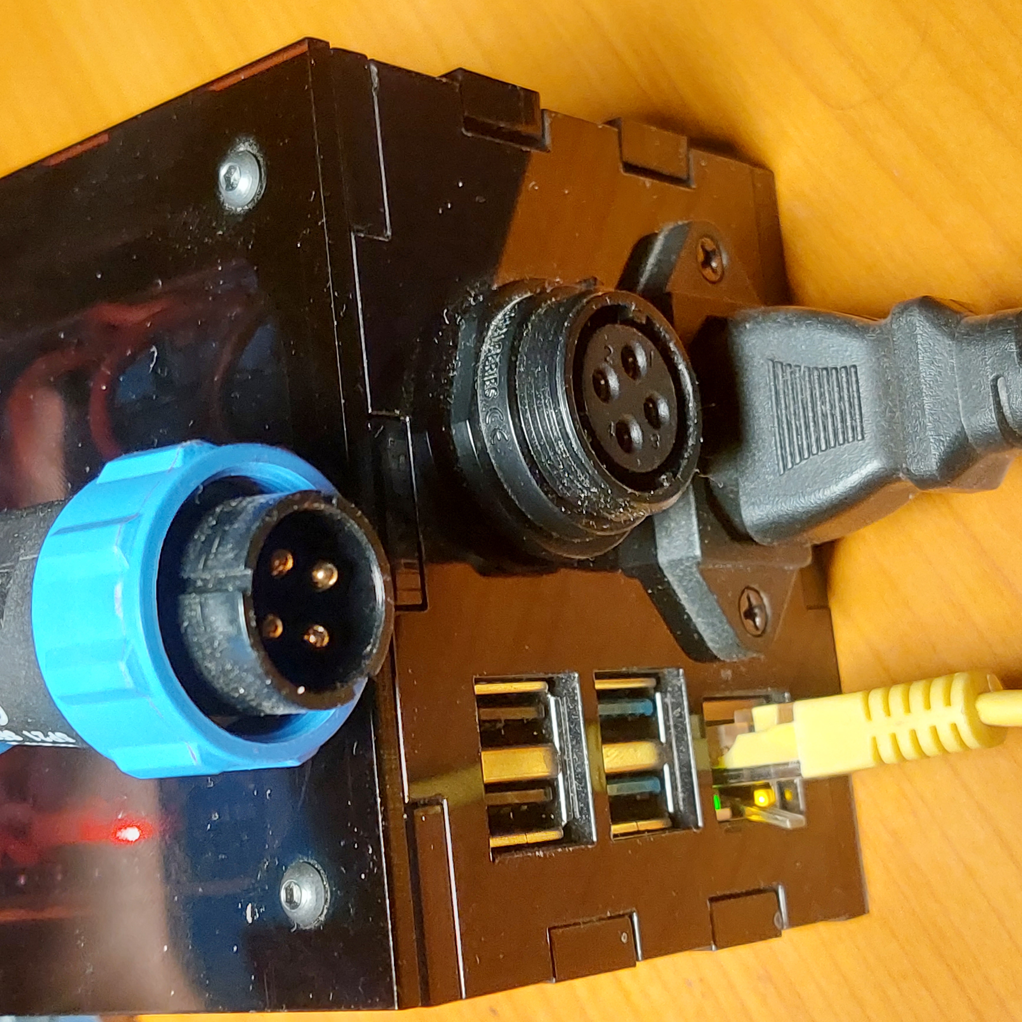
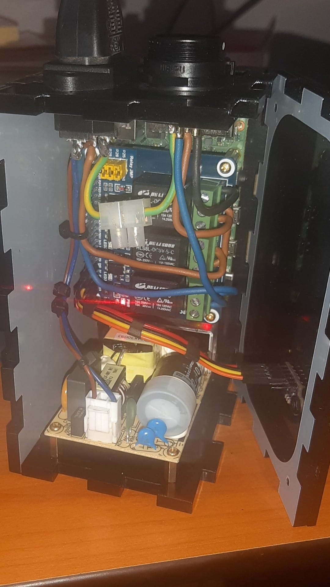
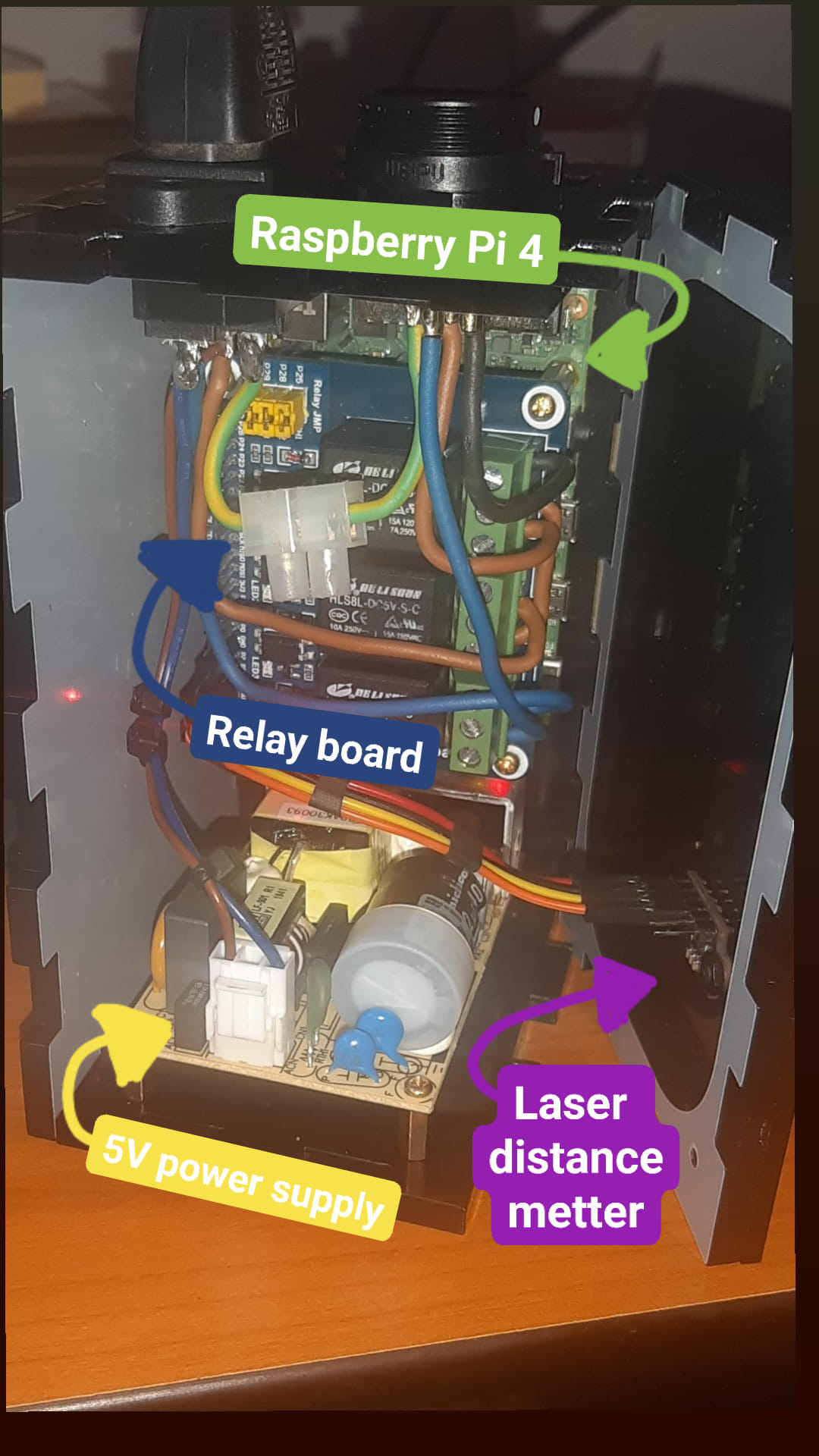
The Driving Control Module (DCM) is an electronic component of the Smart Desk Solution Architecture. Its purpose is to serve as a gateway between the server and our analog desk. We essentially cut some cables used for driving motors and connected our own, enabling programmatic control. Additionally, we've incorporated a laser meter sensor inside to measure the current height of the desk, providing real-time height position data. This single device digitalizes your height-adjustable desk by controlling and measuring its height via MQTT messages through the network.
Currently, I do not recommend this housing design, but it can serve as a starting point for the next version. Here are the known issues and lessons we need to consider in the next iteration:
-
This acrylic box design has two significant issues and therefore must be redesigned:
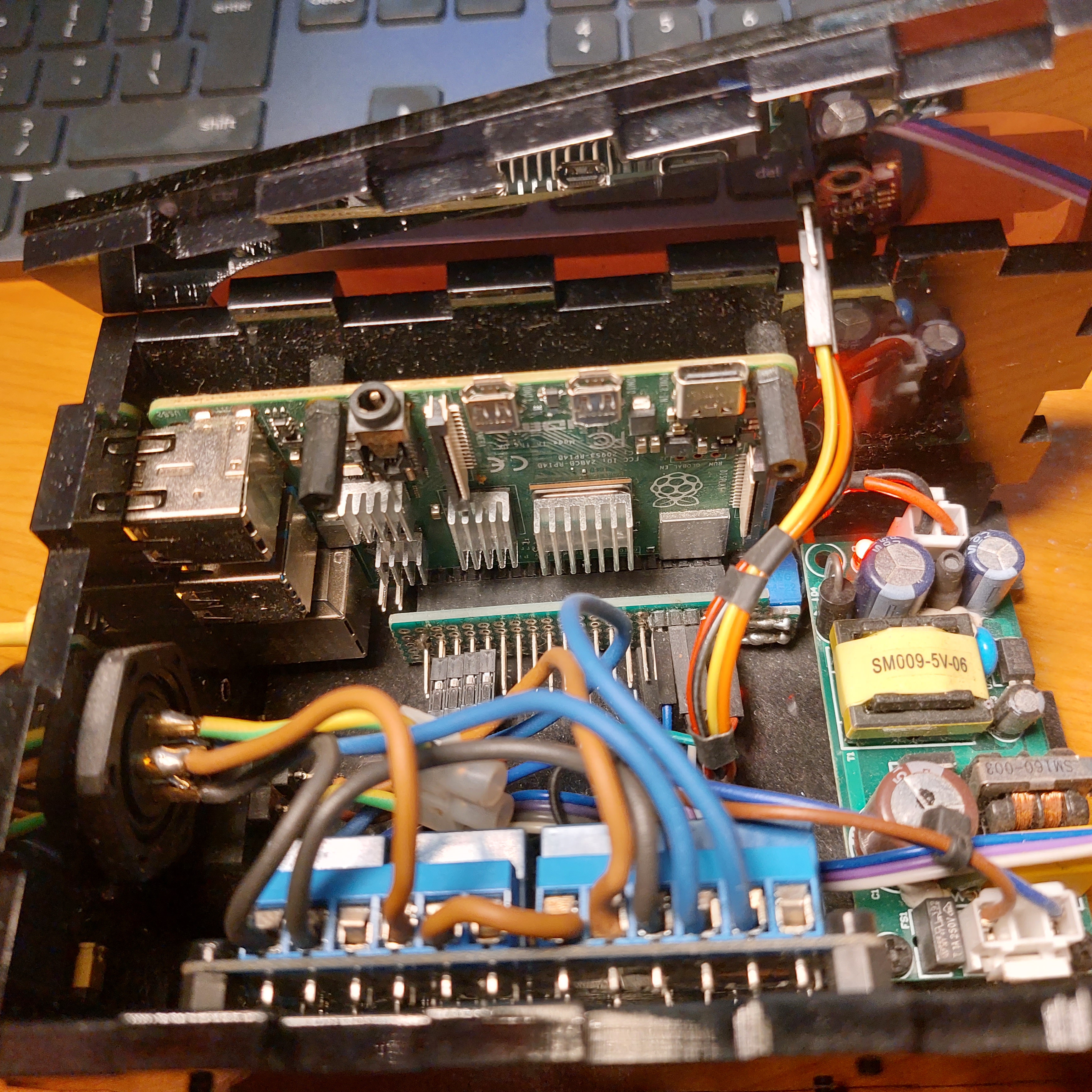
- Lack of airflow leads to electronics overheating. Therefore, I must keep it always open, which is electrically dangerous (no physical isolation from the power supply module to a potential human hand). A better design would require ventilation openings and possibly even forced airflow.
- This enclosure design makes it extremely hard to access and replace important components like RPi or the power supply when the enclosure is glued together. It's not practical at all. We need a construction where easy parts are easy to replace.
- The size is pretty big. There was space for this module on the main desk, but it might not be enough for you. Maybe you would want to attach it under the desk so it's not visible. Therefore, I am now thinking about something simpler and with a separated server microcomputer from the Desk Height Driving Module.
-
Therefore, I will remove this RPi (not to mention that RPi4B can be replaced with a cheaper RPi Zero) and separate the server from the DCM.
-
I've already reduced costs by replacing a 5V power supply from 6A with 2A, which is enough power.
-
We can further reduce costs by removing the RPi and using something simpler like an ESP32 as the microcontroller.
-
Electrical issues: Power jumps when switching relays cause the laser meter to turn off. An electrical engineer is needed.
-
Relay contact issues occurred with one relay board, but not with another. This needs to be kept in mind.
I decided to separate these functionalities into separate modules to allow DIY enthusiasts and manufacturers to easily prepare and integrate custom DCMs into their devices, enabling integration with our ecosystem. Additionally, I wanted to extract the RPi from the high-voltage (230V) controlling driver both for the safety of the RPi to avoid accidental short circuits and to make the architecture more modular. The smart desk server can run on the user's computer in the background, or on a NAS server or another server in an apartment for smart home applications (e.g., with Home Assistant). If the user chooses a separate server for open-smart-desk, they can easily install it on any selected microcomputer, like RPi Zero, and attach it under the desk. The separation of the microcontroller gives flexibility in choosing a machine tailored to their needs, for example, choosing RPi0 for sensors that do not require high computing power or RPi4 if using a camera with ML for body pose recognition and needing more computing power. Hence, the separation of modules gives us a lot of flexibility, integration, and cost reduction.
- Raspbery Pi 4 model B (4GB)
- Waveshare RPi Relay Board (11638)
- Laser metter VL53L0X
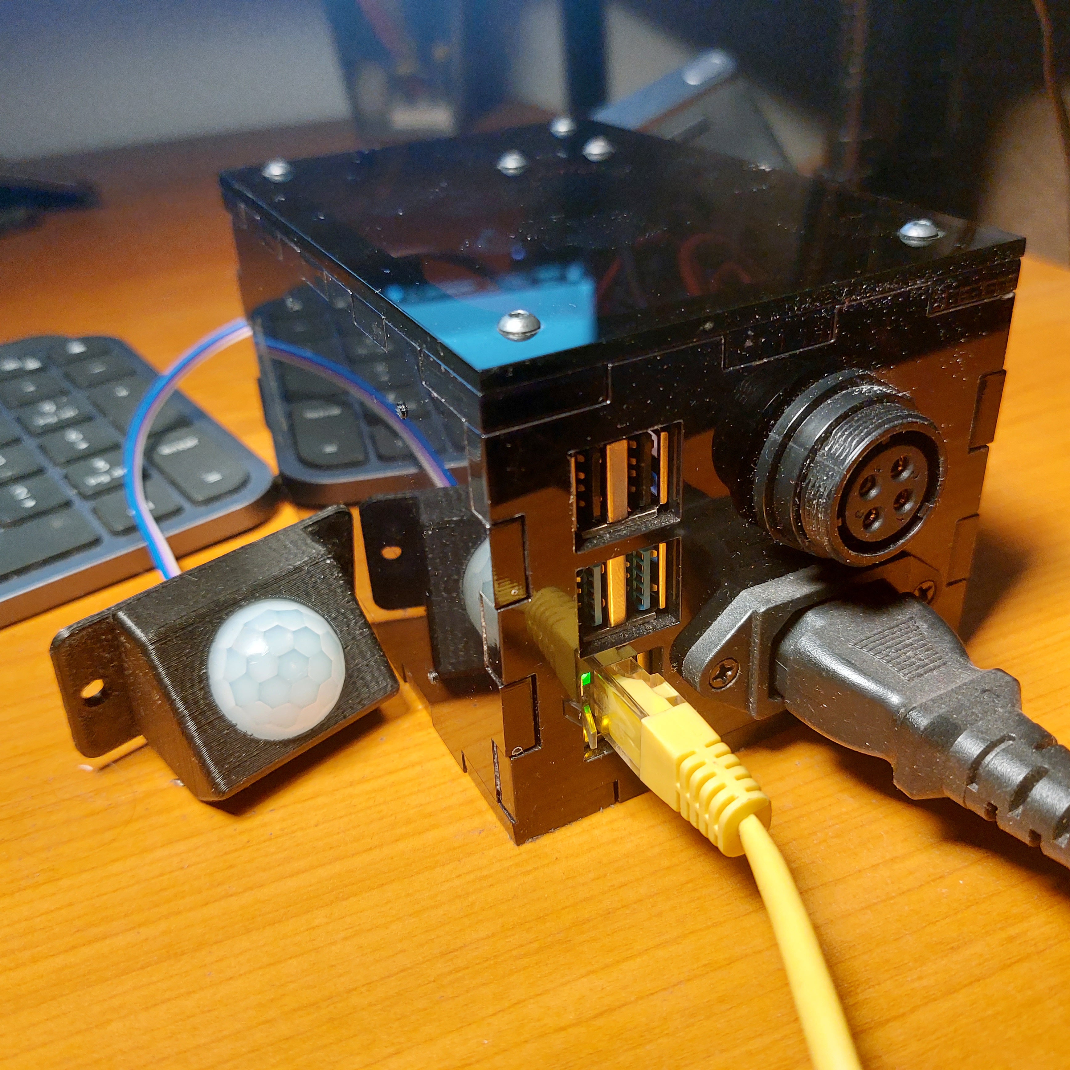
- Motion sensor PIR HC-SR501
- Power supply EPS-35-5 (5V, 6A)
- SP2112/S4 female panel socket
- SP2110/P4II male plug
- 4x low nut M3 (black, oxidized, 3mm height)
- 6x spherical screw M3x8 (black, hex socket)
- C14 male panel socket
- C13 female cable (regular PC power cable)
- microSD card 32GB
- plexi laser cutted enclousre
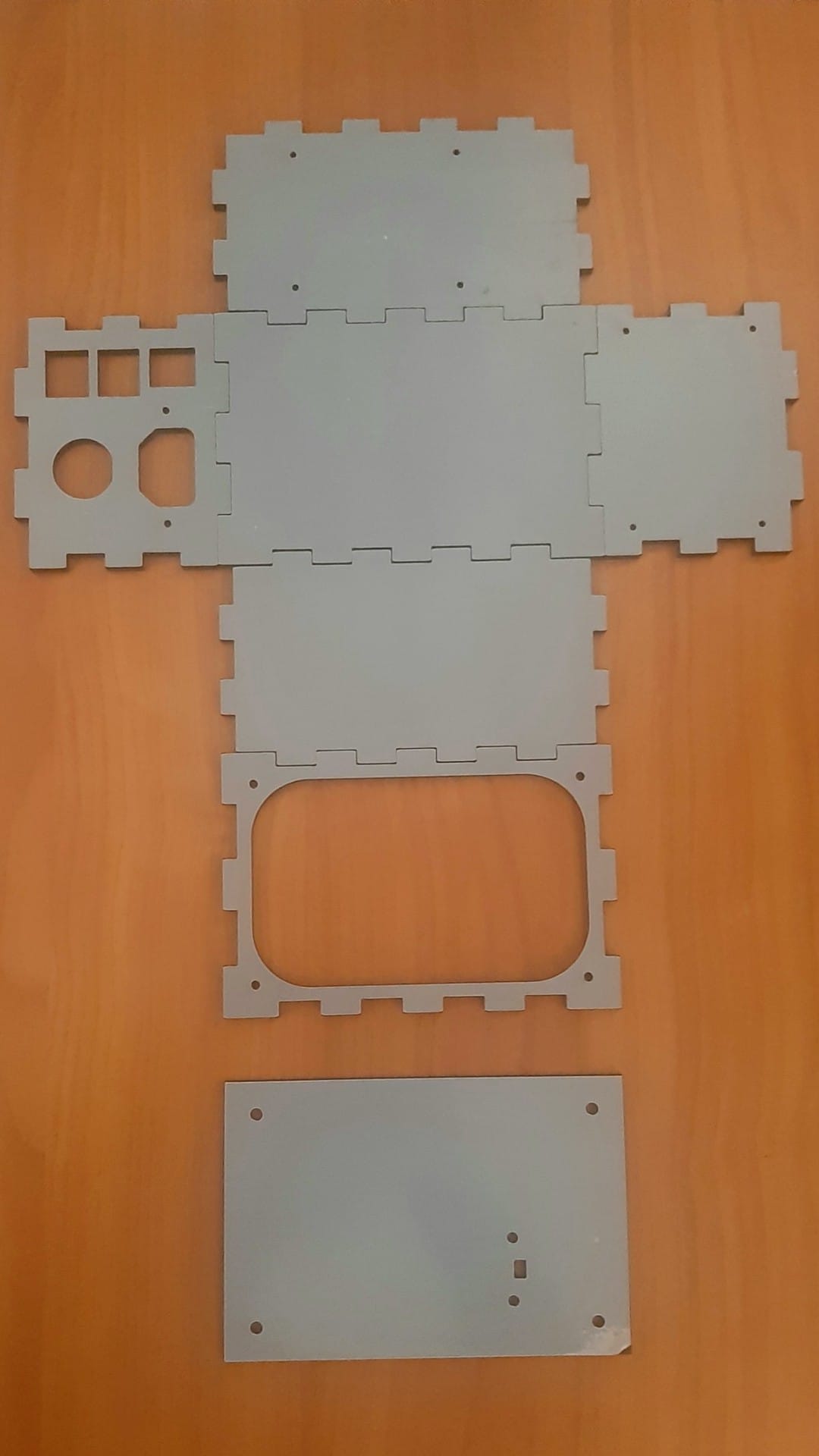
Plexi laser cutted enclousre:
Then I decided to use smaller and cheaper power supply: