-
Notifications
You must be signed in to change notification settings - Fork 74
Home
We are slowly migrating the documentation to https://dvrk.readthedocs.io.

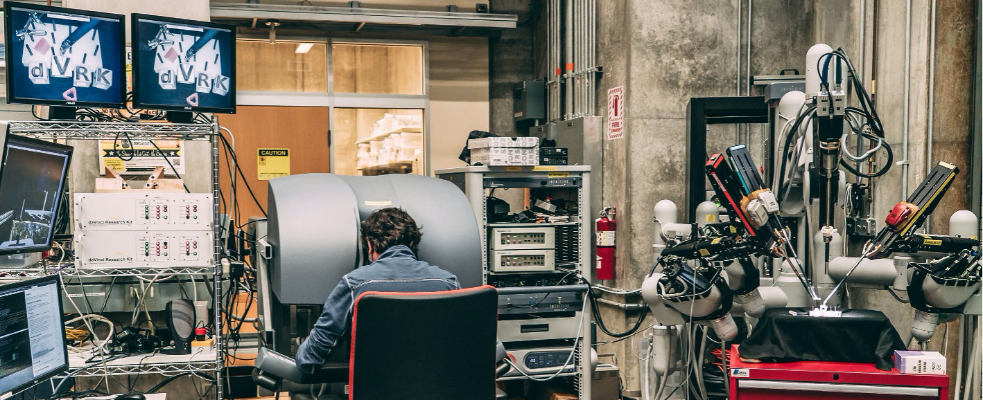
The sawIntuitiveResearchKit folder provides several example applications for controlling the Research Kit for the da Vinci System using the IEEE-1394 (FireWire) controller. The picture above shows a full da Vinci system at JHU that uses the dVRK controllers.
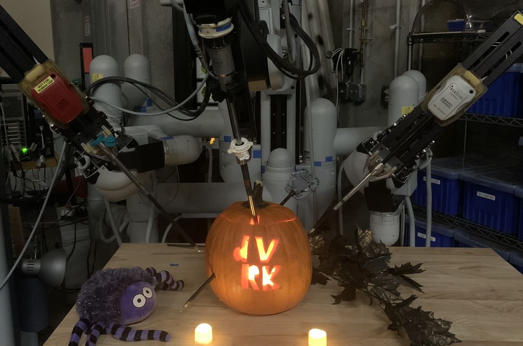
October 31, 2023: The picture below shows some Halloween fun!

Moved to https://dvrk.readthedocs.io
- News from the dVRK community
- Groups and deployment timeline
- Videos of the dVRK in action
- Publications
- Resources:
- Intuitive Foundation: http://www.intuitive-foundation.org/dvrk/ (includes online applications to get retired da Vinci components from Intuitive Surgical)
- github discussions: https://github.com/jhu-dvrk/sawIntuitiveResearchKit/discussions
- Private Google group: https://groups.google.com/d/forum/research-kit-for-davinci and [email protected] (for dVRK owners only; use the Google group web page to request membership, don't forget to mention your group/university so the group admin can identify you)
- Private Intuitive Surgical hardware wiki: http://research.intusurg.com/dvrk (for dVRK owners only)
- Private Slack channel JHU dVRK: https://jhudvrk.slack.com/ (deprecated)
- cisst libraries: http://github.com/jhu-cisst/cisst/wiki
- Johns Hopkins University Mechatronics: http://jhu-cisst.github.io/mechatronics
- List of all JHU LCSR Software: http://jhu-lcsr.github.io/software/
The software applications use some or all of the following cisst/SAW components (and Qt widgets):
- mtsRobotIO1394 - interface to IEEE-1394 (FireWire) controller boards
- mtsPID - PID controller used for MTM and PSM robots
- mtsTeleoperation - Teleoperation components
- mtsTextToSpeech - Text to speech component (for warning and error messages)
Github build status:
The core components are written in C++ and can be compiled on most OSs (Linux, Windows, MacOS). Before the release of the dVRK software 2.0 and firmware 7, FireWire (more specifically libraw1394) was required to communicate with the dVRK controllers so it made little or no sense to compile on dVRK on anything but Linux. We now support UDP over Ethernet Link Local so it is now possible to control the dVRK using Windows or MacOS. This being said, we rely heavily on ROS for most applications so it makes a lot more sense to keep using Linux and more specifically Ubuntu.
A ROS 1 interface is available via mtsROSBridge base class and dVRK ROS programs and files. ROS 2 is supported but not as extensively tested.
Several groups have developed software modules that integrate with the dVRK and may be useful to others in the community. Many of these software modules use ROS to interface to the dVRK.
- Asynchronous Multi-Body Framework (AMBF) - dynamic simulator developed at Worcester Polytechnic Institute (WPI); includes models of the dVRK manipulators and interfaces to the dVRK hardware (e.g., to use MTMs as input devices).
- V-Rep Simulator for the dVRK - V-Rep simulator developed at University of Naples.
- ATAR - Bullet based dynamic simulator developed at Politecnico di Milano.
- dVRL - reinforcement learning environment, based on V-Rep, developed at University of California, San Diego.
- AMBF-RL - reinforcement learning environment, based on AMBF, developed at Worcester Polytechnic Institute (WPI).
- UnityFlexML - machine learning environment, based on Unity 3D, developed at University of Verona.
- SurRoL - reinforcement learning environment, based on PyBullet, developed at The Chinese University of Hong Kong.
- dVRK-XR - mixed reality visualization, based on Unity 3D, developed at Johns Hopkins University; interfaces to dVRK via UDP or ROS.
- Mesh based virtual fixtures - haptic feedback with Slicer visualization, via OpenIGTLink, developed at Johns Hopkins University.
- DVRK_RecordAndPlayback - data recording and playback developed at Wayne State University.
- autocamera - autonomous camera control developed at Wayne State University.
- Instrument tracking
- Stereo reconstruction
Several groups have developed hardware components that integrate with the dVRK and may be useful to others in the community.
-
Instrument force sensor - Force sensor for instrument, described here, developed at Stanford University.
-
MTM force sensor - Force sensor for MTM, described here, developed at University of British Columbia.
Firmware version 6, 7 or 8 is now required (dVRK 2.0+), please upgrade your firmware to 7 or 8 unless you want to use the software versions 1.7.x and 2.x simultaneously. Version 7 adds support for Ethernet/UDP for FPGA 2+ and many other changes. Version 8 adds support for FPGA 3+ and for other controllers (DQLA and DRAC in addition to QLA). See https://github.com/jhu-cisst/mechatronics-firmware/wiki/FPGA-Program for step-by-step instructions to upgrade your firmware.
-
January 2025: Version 2.3.1 released
- Minor updates for cisst, cisstNetlib and crtk_python for Ubuntu 24.04 with ROS 2 Jazzy
- sawIntuitiveResearchKit (main dVRK code and ROS nodes)
- August 2024: Version 2.3.0 released
- December 2023: Version 2.2.1 released
- November 2023: Version 2.2.0 released
- August 2021: Version 2.1.0 released
- April 2021: Version 2.0.0 released
- July 2019: Version 1.7.1 released
- April 2019: Version 1.7.0 released
- May 2018: Version 1.6.0 released
- November 2017: Version 1.5.0 released
- August 2016: Version 1.4.0 released
- January 2016: Version 1.3.0 released
- October 2015: Version 1.2.0 released
- April 2015: Version 1.1.0 released
- April 2014: Moved to GitHub
- May 2013: Initial Public Release
Moved to https://dvrk.readthedocs.io
